PIR Ready VTR7300 Series Terminal Equipment Controller Installation Guide For Commercial and Lodging HVAC F a n C o i l Ap p l i c a t i o n s May 3 rd , 2012 / 028-0298-R8 CONTENTS Installation Location Installation Operation Overview Model Chart Network ready Terminal, Identification and Function Communication wiring to VC3xxxX Relay Pack Network wiring topology VC3xxx LED Operation Wiring of local inputs to VTR73xxA Terminal Equipment Controller Configuring and Status Display Instructions Status displ
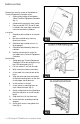
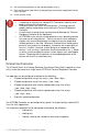
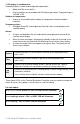
I NSTALLATION Remove the security screw on the bottom of Terminal Equipment Controller cover. Open unit by pulling on the bottom side of Terminal Equipment Controller (fig. 1). Remove wiring terminals from sticker. Please read the FCC ID and IC label installed in the cover upon removal of cover for the wireless products. Location 1. Should not be installed on an outside wall. 2. Must be installed away from any direct heat source. 3. Should not be installed near an air discharge grill. 4.
12. Re-Install wiring terminals in their correct locations (fig. 3). 13. Re-install the cover (top side first) and gently push extra wire length back into the hole in the wall. 14. Install security screw. If replacing an existing Line Voltage FCU Thermostat, label the wires before removal of the thermostat. Electronic controls are static sensitive devices. Discharge yourself properly before manipulating and installing the Terminal Equipment Controller.
2 or 4 pipe only with electric reheat can be configured and wired for the following: o Cooling only o Heating only o Cooling / Heating with network or local auto changeover o On-Off electric reheat only o Cooling with On-Off or modulating VDC pulsed electric reheat ( model dependent ) o Heating with On-Off or modulating VDC pulsed electric reheat ( model dependent ) o Cooling / Heating with network or local changeover with On-Off or modulating VDC pulsed electric reheat ( model dependent )
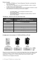
MODEL CHART 5 | PIR Ready VTR7300 Series-Installation Guide
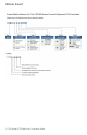
Network ready All Viconics VTR7300 series Terminal Equipment Controllers are designed for stand-alone operation. They can be fully integrated into your choice of automation systems using the available communication adapter options.
From the VTR73xxA to the first VC3xxxX Relay Pack Uses existing or new field wires A minimum of 3 wires are required 14-22 Ga Solid or Stranded. Shield not necessary. From the first VC3xxxX to all other slave VC3xxxX Relay Pack(s) Uses existing or new field wires A minimum of 2 wires are required 14-22 Ga Solid or Stranded. Shield not necessary.
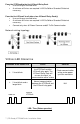
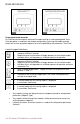
Wiring of local inputs to VTR73xxA Terminal Equipment Controller Local BI 1 Input by configuration: - None (monitoring only) - Remote motion detector: Motion NO or Motion NC - Remote Night Setback: RemNSB - Window contact Window: 13 - BI 1 14 - Scom 15 - BI 2 Local BI 2 Input by configuration: - None (monitoring only) - Door contact: DoorDry VTR73xxA Terminal Controller CONFIGURING AND STATUS DISPLAY INSTRUCTIONS Status display The VTR73xxA Terminal Equipment Controller features a two-line, eight-charac
% RH display is conditional to: (Humidity display is model and configuration dependent) Model with RH sensor built in Display function can be enabled with RH display parameter. Displayed range is 10 to 90 % RH Outdoor air temperature Display is only enabled when outdoor air temperature network variable is received. Occupancy status Occupied, Stand-By, Unoccupied and Override status are displayed on the scrolling display.
USER INTERFACE Unoccupied mode override An Override can be made on commercial models during an unoccupied period. If the Override option is enabled in the lockout configuration, pressing the middle override button will resume occupied setpoints for a time specified by the parameter “ToccTime”. Local keypad interface Is used to toggle between the different system modes available as per sequence and menu selected. Repetitively pressing the button will toggle between all the available modes.
Dual occupied setpoints adjustment (Local occupied setpoint adjustment when “Stp Func” = Dual Stp) AUTO MODE Setpoint presented to user is the setpoint from the last action taken by the Terminal Equipment Controller or the one currently in use. If the other setpoint is the one desired, then the MODE button is used to toggle between the current displayed one and the other. COOLING MODE HEATING MODE OFF MODE Cool XX.X °F or °C Heat XX.X °F or °C No access to setpoint Cool XX.X °F or °C or Heat XX.
AutoMode set to OFF = Auto system mode NOT ACTIVE SEQUENCE SELECTED MODE MENU Off - Cool 0 = Cooling Only 1 = Heating Only Off - Heat 2 = Cooling / Heating Cooling With Electric Reheat Off – Heat – Cool 3 = Heating With Electric Reheat Off - Heat 4 = Electric Reheat Only Off – Heat Available fan button menu sequences FAN BUTTON MENU CONFIGURATION MENU PRESENTED ARE DEPENDENT ON MODEL USED AND SEQUENCE OF OPERATION SELECTED DEFAULT VALUE WHEN SEQUENCE TOGGLED 0 Low-Med-High 3 Speed configuratio
access to all configuration properties of the Terminal Equipment Controller. Entering a wrong password will prevent local access to the configuration menu. Press the same middle button repetitively to scroll between all the available parameters. Use the up and down key to change the parameter to the desired value. To acknowledge and save the new value, press the middle button again. The next parameter will now be displayed.
PAN ID Personal Area Network Identification Default value = 0 Range is: 0 to 1000 Conditional parameter to Wireless models VTR73xxX5x00W This parameter will only appear when a wireless network adapter is present. If the Terminal Equipment Controller is installed as a stand-alone unit or with a BACnet™ or Echelon™ adapter, this parameter will not be used or displayed.
Get From Terminal Equipment Controller Get From another device configuration utility Default value = 0 Range is: 0 to 254 Conditional parameter to Wireless models VTR73xxX5x00W Entering a MAC address enables an automatic routine that automatically fetches all the required configuration properties of the current device from another already configured device an copies the same required configured property values.
BI 2 Binary input no.2 configuration Default value = None (None): No function will be associated with the input. Input can be used for remote network monitoring. (Door Dry) Door contact & Motion detector: This configuration is only functional if binary input #1 is set to Motion NO or Motion NC or a PIR accessory cover is used. With this sequence enabled, the occupancy is now commanded through those 2 inputs. Any motion detected will set the zone to occupied status.
RUI 1 Cont’d Contact opened = No alarm Contact closed = Alarm displayed (Service): A backlit flashing Service alarm will be displayed on the Terminal Equipment Controller LCD screen when the input is energized. It can be tied in to the AC unit control card, which provides an alarm in case of malfunction. RBI 2 Remote Binary input no.2 configuration Default value = None Contact opened = No alarm Contact closed = Alarm displayed (None): No function will be associated with the input.
%RH disp Local %RH Display Default value = Off Models with Humidity sensor only Conditional parameter to Humidity models VTR735xX5x00(X) Enables the display of humidity value below the room temperature value on the display On = Display %RH Off = No display of %RH Lockout Keypad lockout levels Default value = 0 No lock USER KEY FUNCTIONS LEVEL 0 1 2 3 4 5 PulsedHt VDC output configuration Default Value = Off VDC output configuration.
SeqOpera Sequence of operation Default is: Sequence #1 Selects the initial sequence of operation required by the installation type and the application 0 = Cooling Only 1 = Heating Only 2 = Cooling / Heating or Cooling With Electric Reheat 3 = Heating With Electric Reheat 4 = Electric Reheat Only SYSTEM = 2 PIPES SYSTEM = 4 PIPES Available Available Available Available Available Available Cooling With Electric Reheat Cooling / Heating Available Not available Available Not available For 2 Pip
%RH set Conditional parameter to Humidity models Dehumidification setpoint VTR735xX5x00(X) Default is 50 % RH Used only if dehumidification sequence is enabled: Range is: 30-95% RH DehuHyst Dehumidification Hysterisys Default is 5 % RH Conditional parameter to Humidity models VTR735xX5x00(X) Humidity control hysterisys.
Unocc HT Unoccupied heating setpoint Default value = 62 °F Unoccupied heating setpoint range is: 40 to 90 °F ( 4.5 to 32.0 °C ) Unocc CL Unoccupied cooling setpoint limit Default value = 80 °F Unoccupied cooling setpoint range is: 54 to 100 °F ( 12.0 to 37.5 °C ) Heat max Maximum heating setpoint limit Default value = 90 °F ( 32 °C ) Maximum occupied & unoccupied heating setpoint adjustment. Heating setpoint range is: 40 to 90 °F ( 4.5 to 32.
Set Type Temporary setpoint enable Default is : Permnent Enables temporary setpoints feature to any change of occupied or unoccupied setpoint. Temporar: (temporary) Local changes to the heating or cooling setpoints by the user are temporary. They will remain effective for the duration specified by “ToccTime”. Setpoints will then revert back to their default value after internal timer “ToccTime” expires. To change setpoints permanently, revert this variable to No or write setpoints through the network.
Auto Fan Auto Fan Function Default value: AS Auto Speed Fan Mode operation for Fan Sequences 2 and 3 AS = Auto Speed during occupied periods. Fan is always on during occupied periods. AS AD = Auto Speed / Auto Demand during occupied periods. Cool cph Will set the maximum number cycles per hour under Cooling output cycles per normal control operation. It represents the maximum hour number of cycles that the equipment will turn ON and OFF in one hour. Note that a higher C.P.
SPECIFICATIONS Terminal Equipment Controller power requirements: Operating conditions: Storage conditions: Temperature sensor: Temperate sensor resolution: Temperature control accuracy: Humidity sensor and calibration: Humidity sensor precision: Humidity sensor stability: Dehumidification setpoint range: Occ, Stand-By and Unocc cooling setpoint range: Occ, Stand-By and Unocc heating setpoint range: Room and outdoor air temperature display range: Proportional band for room temperature control: Binary inputs
DRAWING & DIMENSIONS Viconics Technologies Inc. Tel.: Fax: Toll free: www.viconics.