VTR8300 User Interface Guide VT8300 Room Controller Series Commercial and Hotel/Lodging HVAC Fan Coil Applications CONTENTS Home Screen Display How to Enter Setup Screen Setup Screen Display Network Settings ZigBee® Network Settings BACnet® Network Settings BACnet® Instance Number Configuration Parameters Setpoints Settings Display Settings User HMI - Hospitality User HMI - Commercial Other Functions Customizable Color Options Setpoint Adjustment Service Views Test Outputs Screen Language Selection 2 3 3
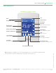
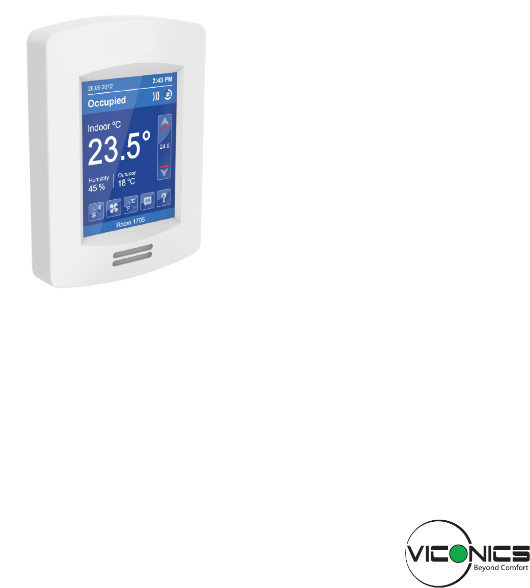
User Interface Guide 2 VTR8300 Series HOME SCREEN DISPLAY Hospitality user interface shown Time Date System Status Occupancy Status Fan Status Up Arrow Raise Temperature Setpoint Room Indoor Temperature Actual Setpoint Room Indoor Humidity Down Arrow Lower Temperature Setpoint Outdoor Temperature Help Enter help screen System Mode Language Select system mode Select preferred language Fan Mode Temperature Units Select fan mode Select Celsius or Fahrenheit units Short Network Messag
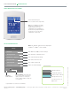
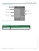
User Interface Guide VTR8300 Series 3 HOW TO ENTER SETUP SCREEN Touch and hold this point for 3 seconds to enter setup mode Note: If a configuration / installer password is activated to prevent unauthorised access to the configuration menu parameters, a password entry prompt will appear to prevent access to the device configuration components. SETUP SCREEN DISPLAY Note: The "Network" button will not be displayed if no BACnet® or ZigBee® card is installed.
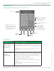
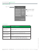
User Interface Guide 4 VTR8300 Series NETWORK SETTINGS ZIGBEE NETWORK SETTINGS (IF ZIGBEE NETWORK CARD IS INSTALLED) Page 1 of 2 1 /2 Z ig b e e n e t w o r k Note: To change the value of a parameter, simply press on the parameter name or value and then use the arrow keys to change the value.
User Interface Guide VTR8300 Series 5 PARAMETER DETAILS (CONT'D) Configuration parameters default value Significance and adjustments ZigBee® channel Channel selection Default value = 10 Range is: 10 to 25 This parameter (Channel) is used to link specific Terminal Equipment Controllers to specific ZigBee® coordinators. For every Terminal Equipment Controller reporting to a coordinator, be sure you set the SAME channel value both on the coordinator and the Terminal Equipment Controller(s).
User Interface Guide 6 VTR8300 Series ZIGBEE NETWORK SETTINGS (CONT'D) Page 2 of 2 2 /2 Z ig b e e o t h e r s Status of the door contact (if installed) Status of the window contact (if installed) Battery alarm of the wireless switch Door status C lo s e d D o o r in s t a lle d No Wi n d o w s t a t u s C lo s e d Wi n .
User Interface Guide VTR8300 Series 7 BACNET NETWORK SETTINGS Page 1 of 2 1 /2 B A C n e t n e t w o r k C OM a d d r e s s 254 N et w o r k u n it s SI N et w o r k la n g . E n g lis h B au d r a t e Auto BACnet status O f f lin e "254" value will set BACnet® network "Offline".
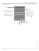
User Interface Guide 8 VTR8300 Series BACNET INSTANCE NUMBER Page 1 of 2 2 /2 B A C n e t in s t a n c e 0 0 8 3 0 Note: The default BACnet® instance number is generated by the model number and COM address of the controller. 5 7 Instance number of the controller. The default instance number will appear first. To change the instance number, use the number pad and then press to save changes made.
User Interface Guide VTR8300 Series 9 CONFIGURATION PARAMETERS 1 /7 C o n f ig u r a t io n BI 1 None BI 2 None RUI 1 None RBI 2 None Occupancy cmd Loc occ. PARAMETER DETAILS Configuration parameters default value Significance and adjustments BI 1 (None): No function will be associated with the input. Input can be used for Binary input no.1 configuration remote network monitoring. Default value = None (Rem NSB): Remote NSB timer clock input.
User Interface Guide 10 VTR8300 Series PARAMETER DETAILS (CONT'D) Configuration parameters default value Significance and adjustments BI 2 (None): No function will be associated with the input. Input can be used for Binary input no.2 configuration remote network monitoring. Default value = None (Door Dry): Door contact & Motion detector: This configuration is only functional if binary input #1 is set to Motion NO or Motion NC or a PIR accessory cover is used.
User Interface Guide VTR8300 Series 11 PARAMETER DETAILS (CONT'D) Configuration parameters default value RBI 2 Remote Binary input no.2 configuration Default value = None Significance and adjustments (None): No function will be associated with the input. Input can be used for remote network monitoring. (Filter): "Filter alarm" will be displayed on the Terminal Equipment Controller LCD screen when the input is energized. It can be tied to a differential pressure switch that monitor filters.
User Interface Guide 12 VTR8300 Series CONFIGURATION PARAMETERS (CONT'D) 2 /7 C o n f ig u r a t io n A uto mo d e E n a b le d F an me n u On-Auto A uto f a n f u n c . AS F an c o n t . h e a t On S tan d b y mo d e Abs S tan d b y d if f . 2 .
User Interface Guide VTR8300 Series 13 PARAMETER DETAILS (CONT'D) Configuration parameters default value Significance and adjustments Fan cont. heat Default is: On Fan control in heating mode. (On): the controller in all cases will always control the fan (terminals LowMed—Hi Fan Speed). Valid in any fan sequences and all the available fan modes. (Off Auto): the controller in all cases will disable the fan (any terminals LowMed—Hi Fan Speed). ONLY when the local fan mode is set to Auto.
User Interface Guide 14 VTR8300 Series CONFIGURATION PARAMETERS (CONT'D) 3 /7 C o n f ig u r a t io n These parameters are model dependent and may not appear on certain models. S ta n d b y t ime 0 .5 h r s U n o c c . t ime 0 .0 h r s Tem p . o c c . t ime 2 .0 h r s D eh h y s t e r e s is 5 .0 % R H D eh . ma x c o o l 100% D eh . lo c k o u t E n a b le d PARAMETER DETAILS Configuration parameters default value Standby time Default 0.
User Interface Guide VTR8300 Series 15 PARAMETER DETAILS (CONT'D) Configuration parameters default value Deh. max. cool. Default value = 100 % Significance and adjustments Maximum cooling valve position when dehumidification is enabled. This can be used to balance smaller reheat loads installed in regards to the capacity of the cooling coil. Range is: 20 to 100 %. (Models with humidity sensor only). Deh. lockout Default value: Enabled Dehumidification lockout, typically toggled through the network.
User Interface Guide 16 VTR8300 Series CONFIGURATION PARAMETERS (CONT'D) 4 /7 C o n f ig u r a t io n C oo l C P H 4 H ea t C P H 4 C oo lin g v a lv e NC H ea t in g v a lv e NC PARAMETER DETAILS Configuration parameters default value Cool CPH Default value = 4 C.P.H. Significance and adjustments Cooling output cycles per hour. Will set the maximum number cycles per hour under normal control operation.
User Interface Guide VTR8300 Series 17 CONFIGURATION PARAMETERS (CONT'D) 5 /7 C o n f ig u r a t io n Prop. band 3 .0 P ul s e d h e a t in g Off Pipe no. 2 S eq. o p e r a t io n Heat P urg e s a mp le 2 .0 h r s P urg e o p e n 2 min PARAMETER DETAILS Configuration parameters default value Significance and adjustments Prop. band Default is : 3 Proportional band setting. Adjusts the proportional band used by the Terminal Equipment Controller PI control loop.
User Interface Guide 18 VTR8300 Series PARAMETER DETAILS (CONT'D) Configuration parameters default value Significance and adjustments Pipe no. Default is: 2.0 Pipes System type installation: Number of pipes. Defines the type of system installed. Seq. operation Default is: Heat Selects the initial sequence of operation required by the installation type and the application.
User Interface Guide VTR8300 Series 19 CONFIGURATION PARAMETERS (CONT'D) 6 /7 C o n f ig u r a t io n M ain p a s s w o r d 0 U se r p a s s w o r d 0 C al ib . t e mp . 0 .0 C C al ib . h u mid . 0% RH Parameter only displayed on models with built in humidity sensor. PARAMETER DETAILS Configuration parameters default value Main password Default value = 0 Significance and adjustments Installer’s password.
User Interface Guide 20 VTR8300 Series CONFIGURATION PARAMETERS (CONT'D) 7 /7 R e in it ia liz a t io n E r a s e a ll ? no A re y o u s u r e ? no P us h t o a c c e p t Accept changes PARAMETER DETAILS Configuration parameters default value Significance and adjustments Erase all ? Are you sure ? Default values = No Answering “Yes” to these two questions and pressing the “Accept” button, will erase all values to factory’s default values except networked related values: © 2014 Viconics Technol
User Interface Guide VTR8300 Series 21 SETPOINT SETTINGS 1 /2 S e t p o in t s U no c c . c o o l. 2 6 .5 ° C S tan d b y c o o l. 2 5 .5 ° C Occ . c o o l. 2 4 .0 ° C Occ . h e a t . 2 2 .0 ° C S tan d b y h e a t . 2 0 .5 ° C U no c c . h e a t . 1 6 .5 ° C PARAMETER DETAILS Configuration parameters default value Significance and adjustments Unocc. cool. Default value = 26.5 °C ( 80 °F ) Unoccupied cooling setpoint range is: Standby cool. Default value = 25.
User Interface Guide 22 VTR8300 Series SETPOINT SETTINGS (CONT'D) 2 /2 S e t p o in t s D ef a u lt h e a t 2 6 .0 C Mi n. d e a d b a n d 1 .5 C Max . h e a t in g 3 2 .0 C Mi n. c o o lin g 1 2 .0 C D eh u mid if y 50% RH Parameter only displayed on models with built in humidity sensor. PARAMETER DETAILS Configuration parameters default value Default heat Default value = 22.
User Interface Guide VTR8300 Series 23 DISPLAY SETTINGS 1 /2 D is p la y U ser H M I 0 Color W h it e M ai n d is p la y Te mp . S tan d b y s c r e e n No PARAMETER DETAILS Configuration parameters default value User HMI Default value = 0 Significance and adjustments Select user HMI type. Range: 0 to 11. User HMI - Hospitality 1 (Hospitality) 2 (Hospitality) 3 (Hospitality) © 2014 Viconics Technologies. All rights reserved.
User Interface Guide 24 VTR8300 Series User HMI - Hospitality 4 (Hospitality) 5 (Hospitality) 6 (Hospitality) 8 (Commercial) 9 (Commercial) User HMI - Commercial 7 (Commercial) 10 (Commercial) 11 (Commercial) Note: The day/nite setback button appears only in unoccupied mode from © 2014 Viconics Technologies. All rights reserved. 7 to 11 in HMI Commercial. If BI2 input is configured as "override", then the day nite setback button won't appear.
User Interface Guide VTR8300 Series 25 Other functions RH Display = Configuration + model dependent Outdoor Temp = When set by network Heating only If main display parameter is set to "setpoint", the setpoint value will display as shown: Time and Date will display only if it has been properly set (from the network) © 2014 Viconics Technologies. All rights reserved. On/Off will display when the sequence of operation is set to heating or cooling only Viconics Technologies Inc.
User Interface Guide 26 VTR8300 Series Setpoint Adjustment Cooling mode or cooling only sequence of operation In Cooling mode, the setpoint displayed in the bar is the current occupied cooling setpoint. During occupied setpoint adjustment, the large digits are temporarily used to display the occupied cooling setpoint while it is adjusted. Normal temperature display resumes after the setpoint is adjusted and the actual occupied cooling setpoint is displayed in the setpoint bar.
User Interface Guide VTR8300 Series 27 PARAMETER DETAILS (CONT'D) Configuration parameters default value Color Default value = Blue Significance and adjustments Select user HMI color. Other choices: Green, Dark Grey, Grey and White. Main display Default value = Temp. Select default value displayed on main display: Temperature or setpoint. Choices: Temperature or setpoint. Disp. cust. img. Default value = No Selecting "Yes" will display a custom image after 2 minutes of touch screen inactivity.
User Interface Guide 28 VTR8300 Series DISPLAY SETTINGS (CONT'D) 2 /2 D is p la y Lan g u a g e E n g lis h U ni t s °C Lo w b a c k lig h t 60% N i g h t b a c k lig h t 5% R H d is p la y D is a b le d Parameter only displayed on models with built in humidity sensor. PARAMETER DETAILS Configuration parameters default value Significance and adjustments Language Default value = English Select language for main display.
User Interface Guide VTR8300 Series 29 SERVICE VIEWS The service view screens show the current status of certain points locally at the controller. These points can also be viewed through the network. 1 / 6 S e rv i c e v i e w Firmware revision of the controller Changeover temperature Outdoor temperature F ir mw a re re v. 1.0 Ro om t e mp . xx.x °C UI19 C h g O v e r xx.x °C UI20 R S t e mp . xx.x °C Ou t d o o r t e mp . xx.x °C Ro om h u mi d i t y xx.
User Interface Guide 30 VTR8300 Series SERVICE VIEWS (CONT'D) 3 / 5 S e rv i c e v i e w Binary 1 input Remote universal input 1 BI 1 Not activ BI 2 Not activ RUI 1 Activated RBI 2 Activated Binary input 2 Remote universal input 2 4 / 6 S e rv i c e v i e w Filter alarm Dehumidification Wind o w a l a rm Off S erv i c e a l a rm Off F ilte r a l a rm Off L o c a l mo t i o n On Deh . s t a t u s Off Service alarm Local motion (on board detector) © 2014 Viconics Technologies.
User Interface Guide VTR8300 Series 31 SERVICE VIEWS (CONT'D) 5 / 5 S e rv i c e v i e w Dev i c e n a me : Note: This represents BACnet® device name automatically assigned using the current BACnet® MAC address. VTR83xxAxxxx The network can update and change the device BACnet® name.
User Interface Guide 32 VTR8300 Series LANGUAGE SELECTION L an g u ag e S el ect i o n F r en ch Enabled S p an i sh E na b l e d C h i n ese Enabled R u ssi an Enabled © 2014 Viconics Technologies. All rights reserved. All languages are enabled by default, which means that they will be accessible to users cycling through languages on the display settings menu screen.