VW A5 0 0 0 Se r ie s W ir el e ss D oo r & W in dow Sw itc h Ins t a ll ati on G ui de th June 20 , 2012 / 028-0321-R6 CONTENTS Installation Self Testing Location Operation Overview Model Chart Pairing Process Procedure Configuring Actions Using the VTR7300 Controllers for Stand-alone Systems Using the VTR7300 Controllers for Networked Systems Important Notes Before Starting Pairing Procedure Steps to Associate Switches with Controllers Multiple Switch configuration Troubleshooting Guide Status & Monitor
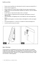
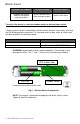
I NSTALLATION Remove cover by pulling on the side where the security screw was mounted (Fig. 1). Remove cover of magnet unit. Please read the FCC ID and IC label installed in the cover upon removal of cover. Prepare and cut the mounting template supplied at the end of this manual for optimal performance. Do NOT place on hinge side of the door. (Unless self tested) Set the template as required and mark the required 4 hole locations for the self tapping screws.
LOCATION 1. The switch unit should never be installed on a moving part (door or window). 2. Only the magnet unit should be installed on a moving part (door or window). 3. Should not be affected by direct sun radiation. It may affect the color over a long period of time. 4. Ensure that the minimum distance between any Viconics wireless node and any Wi-Fi devices ( wireless routers, wireless adapters, lap-tops using wireless networks, etc….
O PERATION OVERVIEW The VWA5000W series Zigbee™ wireless switches are used in conjunction with the wireless versions of the VTR73XX Series Fan Coil Terminal Equipment Controllers. A typical hospitality application is where the VTR73xx wall terminal equipment controller has an on-board PIR sensor and wireless switches are used to monitor opening and closing of entry doors & windows.
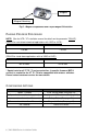
MODEL CHART VICONICS PART NUMBER VWA5000W5000W VWA5000D5000W Complete with magnet, batteries and required mounting hardware Wireless Window Switch (Patio and balcony doors) Wireless Door Switch To verify if the device is a wireless window switch or wireless door switch: - Power cycle the switch (remove battery for 60 seconds and then insert again) and verify the LED blinking pattern to confirm if it is a window switch or door switch or simply read the label located on the electronic board.
Magnet Magnet Housing Fig.5 – Magnet Components and Proper Magnet Orientation P AIRING P ROCESS P ROCEDURE NOTE: (See the VTR / VT installation manual for details on the parameter “PAN ID”). (PAN ID for centralized networked applications with VWG or JACE): VTR7300 Series VT 72 / 73 Series* 1 to 500 1 to 250 (PAN ID for stand-alone applications with no VWG or JACE): VTR7300 Series VT 72 / 73 Series* 501 to 1000 251 to 500 * Special note for all VT 72 / 73 series controllers.
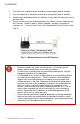
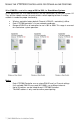
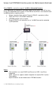
U SING THE VTR7300 CONTROLLERS FOR STAND - ALONE SYSTEMS When PAN ID is used with a range of 501 to 1000, for Stand-Alone Systems In this application, the VTR7300 controller(s) are the coordinators to their own system. I.E. They are the network masters for each wireless switch reporting to them. A unique network is needed for proper functionality. Wireless controller factory default Channel & PAN ID = controller(s) offline. Each VTR7300 controller is its own network coordinator.
Typical floor plan of a unique network for Stand-Alone systems with VTR7300 Controllers: 8 | VWA 5000 Series-Installation Guide
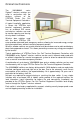
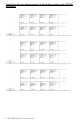
USING THE VTR7300 CONTROLLERS FOR N ETWORKED S YSTEMS When PAN ID is used with a range of 1 to 500, for Networked Systems In this application, any controller(s) are simply routers to the system. The VWG or JaceDriver is the coordinator to the system. I.E. the VWG or Jace-Driver is the network master for ANY controller(s) reporting to them. Wireless controller factory default Channel & PAN ID = controller(s) offline. VWG Jace-Driver is the network coordinator. VTR7300 controllers act as a router.
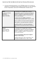
IMPORTANT NOTES BEFORE STARTING P AIRING PROCEDURE Verify that the following parameters on the VTR7300 controller are set correctly to avoid failure in associating the wireless switch to the controller. For more information on the list of parameters, refer to the VTR7300 controller installation manual. PAN ID Personal Area Network Identification Default value = 0 Range is: 0 to 1000 This parameter will only appear when a wireless network adapter is present.
STEPS TO ASSOCIATE SWITCHES WITH CONTROLLERS 1) Pull off the pull tab from the battery holder to power the switch. 2) Verify or set configuration parameter “BI1” or “BI2” to “None”. This sequence will erase the current associated devices. 3) Set the configuration parameter “BI1” to “Window” & “BI2” to “DoorDry” as required. 4) If previously associated, to reset the wireless switch to its factory default settings, simply short the switch (use a metal ball point pen) and hold for 20+ seconds.
MULTIPLE SWITCH CONFIGURATION In a multiple switch configuration, up to 20 switches can be linked to one controller. Repeat steps 5 to 9 in the pairing process procedure to add multiple wireless switches. When a multiple switch configuration is modified i.e. removing a switch, a RESET is required. Please follow these steps: 1) Reset the wireless switch to its factory default settings, simply short the switch (use a metal ball point pen) and hold for 20+ seconds. 5 short blinks will confirm reset.
STATUS & MONITORING Once the switch is commissioned, it can be monitored by the status LED when diagnostic mode is enabled. Once diagnostic mode is enabled, when the magnet is placed near the switch, the LED will be off and when the magnet is away from the switch, the LED will be on. The switch status can also be viewed as a present value on the network front end.
BATTERY STATUS To verify the battery strength of the wireless switch, simply jump the switch for 4+ seconds and less than 10 seconds and a blinking pattern will be displayed. After the blinking pattern is displayed, the switch will enter diagnostic mode for duration of 10 seconds (See Status & Monitoring, page 12).
S PECIFICATIONS Power requirements: 3.0 VDC 2 x AAA batteries. Factory supplied Operating conditions: 0 °C to 50 °C ( 32 °F to 122 °F ) 0% to 95% R.H. non-condensing Storage conditions: -30 °C to 65 °C ( -22 °F to 122 °F ) 0% to 95% R.H. non-condensing Agency Approvals all models CE: RTTE 1999/5/EC Agency Approvals Wireless models FCC: Compliant to: Part 15, Subpart C THIS DEVICE COMPLIES WITH PART 15 OF THE FCC RULES.
DRAWING & DIMENSIONS Switch & Switch Base Dimensions Magnet & Magnet Base Dimensions Viconics Technologies Inc. Tel.: Fax: 16 | VWA 5000 Series-Installation Guide Toll free: www.viconics.
MOUNTING TEMPLATES Location of security screw NOTE: The magnet is to be placed on the opposite side of the security screw of the switch (Opposite side of the batteries).
Location of security screw NOTE: The magnet is to be placed on the opposite side of the security screw of the switch (Opposite side of the batteries).