VWG-50-5000 Viconics Wireless Gateway Setup Guide January 10th, 2012 / 028-367-R1 CONTENTS Disclaimers Trademarks Overview Parts Available Compatibility & History Revision Table Compatibility Overview About Viconics Wireless Mesh Networks Basic Initial Design and Deployment Consideration 6A stands for a maximum 6 addresses per device / node / controller. Orphan Nodes. 5H stands for 5 hops maximum recommended.
DISCLAIMERS NO WARRANTY. Viconics, Inc. (herein after referred to as “Viconics”) makes no warranty as to the accuracy of or use of this technical documentation. Any use of the technical documentation or the information contained therein is solely at the risk of the user. Documentation may include technical or other inaccuracies or typographical errors.
Ferrites supplied with the power supply and VWG MUST be installed according to instructions. Failure to do so may void the FCC compliance of the VWG and wireless controllers. Only VWG-PS-DC and VWG-PS-AC power supply can be used with the VWG. The usage of another non-approved power supply may void the FCC compliance of the VWG and wireless controllers. THIS DEVICE COMPLIES WITH PART 15 OF THE FCC RULES.
PARTS AVAILABLE Part number Description Viconics BACnet™™ over MS-TP & IP wireless gateway.
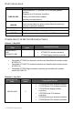
Compatible VT7200 Series zone wireless controllers are identified with wireless module 051-0083 Rx Compatible VT7300 Series FCU wireless controllers are identified with wireless module 051-0083 Rx Compatible VT7600 Series staging wireless controllers are identified with wireless module 051-0083 Rx Compatible VTR7300 Series FCU wireless controllers are identified with wireless module 051-0083 Rx Compatible VZ7200 Series zone wireless controllers are identified with wireless module 051-0070
ABOUT VICONICS WIRELESS MESH NETWORKS The Viconics Wireless Gateway (VWG) and related wireless controller family (VT7xxxXxxxxW) networkable devices operate using Zigbee™ ™/IEEE 802.15.4 physical layer for communication. General characteristics of the wireless physical communication layer are: Uses a wireless physical layer of 2.
A maximum of 50 networkable controllers can be supported by a single VWG. Database creation and configuration is easily made using a Viconics software appliance that communicates with the VWG. BASIC INITIAL DESIGN AND DEPLOYMENT CONSIDERATION IMPORTANT: It is HIGHLY recommended that you do a proper field survey with the Viconics survey tools to establish connectivity limitations and architecture layout on ALL job sites considered for deployment with the Viconics wireless controller products.
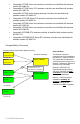
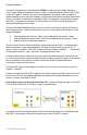
A Zigbee™ device / node / controller is said to have successfully joined a network if it can obtain a Zigbee™ network address from the main VWG coordinator or any other router devices / nodes / controller. 6A stands for a maximum 6 addresses per device / node / controller. Any given device / node / controller including the VWG –coordinator can ONLY give a maximum 6 Zigbee™ addresses out to other devices so they join the active Zigbee™ network.
Orphan Nodes. As such it is important to understand that HOW the network is first initially started up “may” create orphan unassigned devices / nodes / controllers that will seem to NOT want to join the Zigbee™ network. Let’s first understand how an orphan node is created. A typical example is when jobs are started on a technician desk before sending the devices / nodes / controllers in the field for installation.
Premises: Building A is first stated. Yellow device / node / controller have given out its 6 addresses to other devices in building A. Building B devices / nodes / controllers can only be connected through blue device / nodes / controller due to maximum distance coverage. Result: Orange devices / nodes / controllers cannot join the Zigbee™ network.
5H stands for 5 hops maximum recommended. 5H is for a simple process when laying out the architecture of the network. ANY given device / node / controller should be “optimized” to be NO FURTHER IF POSSIBLE than 5 Hops to & from the VWG / Coordinator. This is due to the nature of the Viconics Zigbee™ stack in the wireless controllers.
Proper design considerations need to be addressed prior to any installation of a Viconics Wireless Gateway (VWG) and related wireless controllers. 1. 2. To properly avoid network interference with 802.11 Wi-Fi devices in the 2.4GHz spectrum range, Viconics recommends the use of 802.15.4 channels 25 and 26 only. 802.11 Wi-Fi transmissions overlap and may interfere with other channel selection allowed by 802.15.
Non line of sight, typical wall gypsum wall partitions made with metal stud frame should be under 50 feet ( 15M ) 3. Ensure that the minimum distance between any Viconics node and any Wi-Fi devices (wireless routers, wireless adapters, lap-tops using wireless networks, etc….) to be at least 3 foot (1 M) and preferably 10 feet (3 M) or more.
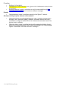
4. 5. 6. 7. 8. 9. Ensure that at least one controller is within 50 feet of the VWG for every cluster of 10 controllers installed. Always try to locate if possible the VWG near the center of all associated wireless controllers. Always try to locate the VWG near on in line of sight to as many wireless controllers as possible. Try to avoid metal, brick walls or concrete obstructions between wireless devices as much as possible. Make sure the antenna on the VWG is always perpendicular to the floor.
50 feet (15 M) 15 | VWG-50-Setup Guide
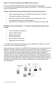
GATEWAY CONFIGURATION Initial Connection The setup will guide you through the necessary installation steps. The minimum system requirements for installation are: An Ethernet adapter with TCP/IP support. A WEB browser installed. (Google Chrome or Firefox recommended) An Ethernet TCP/IP connection to the VWG is required for commissioning.
Recommended setting for java Open the java control panel and on the advanced tab under the "Java Plug-In" and disable the "next generation Plug-In " which might solve your issue. Go to the control panel of the machine Click on “java”, this opens the java control panel In the java control panel click on the “advanced” tab, then view under “Java Plug-In”.
Once logged into the webpage: Note: During anytime a page loads, do not perform another command (re-click) or recall the same function twice. DO give time for the pages to remotely load normally. Not doing so “can” cause the system to hang or go down. If this happens, a simple browser reboot will be necessary. Click on the “User Manager” tab, to edit the username and password, click on the “Edit” button. This step can be skipped and left as is. Next, click on the “General Settings” tab.
VWG Zigbee™ Settings These settings are where you set the Zigbee™ PAN ID (Personal Area Network Identification) address and the channel for the wireless network. Gateway Wireless PAN ID. (Personal Area Network Identification). This is where the PAN ID of the gateway is set. Range is from address 1 to 500. The default of “0” is not a valid PAN ID. Wireless Channel. This is where the current Channel frequency used by the gateway is set. Range is from 11 to 26.
Point Name Convention.
BACnet Settings Use this tab for general BACnet IP and MSTP settings of the gateway.
Broadcast Distribution Table Manager When the station is operating as a BBMD, Niagara maintains this table listing all other participating BBMDs, including their IP address and broadcast distribution masks. If necessary, this view allows you to manually edit the BDT. Foreign Distribution Table Manager When the station is operating as a (BACnet) "foreign device," this table lists all other BACnet foreign devices that have registered with Niagara, including their IP address, time to live, and purge time.
BACnet IP Settings BACnet Adapter. This selects which of the 2 IP network connections is to be used for BACnet IP communication. Net1 or Net2. The default is set to Net 1. UDP Port. Is the default BACnet UDP port number assigned to the device if the VWG for BACnet IP communication. The default port for BACnet communication port used is: 47808 (0xBAC0). Do not change this value Bbmd Address. The BACnet IP Address of the BBMD this foreign device should register with.
BACnet Settings. BACnet MS-TP Settings MS-TP Address. Is the BACnet MAC address assigned to the VWG. It is a unique identification number of a device on a BACnet MS-TP network and needs to be unique on that RS-485 trunk. Usable MS-TP MAC range is from 0 to 127. Default is value is –1, which disables BACnet MS-TP communication. MS-TP Baud Rate. Is the assigned Baud rate of the VWG on the BACnet MS-TP networks.
Wireless Controller / Controllers Manager This is where the wireless controllers are discovered and then added to the database together with the associated points for each device. Toolbar Click on the “Discover” button and set the range of the com addresses. EX: (Discover controllers in the range of com address from 1 to 100) PLEASE NOTE: During the process of adding or removing “many” controllers at once, the tool “may” not respond to new inputs while the process is active.
If a particular controller refuses to join the network and cannot be seen by the VWG. Please move momentarily closer to the VWG until it has joined the network and it is added to the database. It can then be re-located to its original position. This is necessary for it to be assigned a Zigbee™ address to join the network. Note: For more information on “orphan nodes” and Zigbee™ connectivity, please refer to document: 028-0297_Rx_MAN VST5000W5000W-Exx.
Address. The current physical MAC address set at each individual controller in its local configuration. Name. The controller’s given name in the database. The name is constructed of the controller model number and its current local MAC address. Ex. A VT7300C5x00W with a local MAC address of 21 will carry a name in the database of VT7300C5x000_21 Added to Network o True = controller already added to the database.
BACnet Points Viewer This shows all the of the point objects that are loaded on the VWG BACnet export table from each controller BACnet points include: Analog Values Binary Values Multistate Values The displayed BACnet object names are displayed as configured by the installer from the general parameters section, under point name convention. To view only the objects from any specific controller; in the “Controller Manager” tab, double click on the icon.
Additional Options The default name of discovered controller is “Model#_Address”. To change the name, enter the controller manager tab, right hand click on the desired controller and click “edit”. ** The Zigbee™ address and IEEE address information can also be seen. To delete a controller from the database, simply select the device and click on the “delete” button. This option also deletes it from the discovered controllers field. The controller can always be re-discovered if needed. Module Version.
General TCP/IP Configuration Hostname. Is the local hostname exposed on the network. Please do not change and leave to “Localhost” DNS Domain. The TCP/IP Domain Name System (DNS) domain this host belongs to. Only if DNS is used. IPv4 Gateway. The IP address for the device that forwards packets to other networks or subnets. DNSv4 Servers. The IP address for one or more DNS servers, each of which can automate associations between hostnames and IP addresses.
DHCPv4. A checkbox to specify DHCP (Dynamic Host Configuration Protocol) instead of static IP addressing. Successful use requires a DHCP server installed on your network. If enabled, other interface fields such as IP Address and Subnet Mask become read-only, as the DHCP server assigns these after the platform reboots. Note: In general (for stability), static IP addressing is recommended over DHCP.
TIPS AND THINGS YOU NEED TO KNOW Be sure all controllers / controllers communicating to any single VWG are using the same PAN ID and Channel as the VWG wireless communication card found & set in the property sheet. Room Temperature, Outdoor Temperature and Room Humidity need to have their Boolean override counterpart object set to “Override” first if the present value needs to be written over from the network.
VWG Wireless Adapter LED Status Indicators 1 x ( 200ms ) short blink 2 x ( 200ms ) short blinks 3 x ( 200ms ) short blinks 4 x ( 200ms ) short blinks Power on Power on and card memory initialized properly Power on, card memory initialized properly and serial communication with the VWG main board active Power on, card memory initialized properly, serial communication with the VWG main board active and wireless networks started successfully Power on, card memory initialized properly, serial communication wit