VWG-50-5000 Viconics Wireless Gateway Hardware Installation Guide January 10th, 2012 / 028-0369-R1 CONTENTS Disclaimers Trademarks Overview 3 Parts Available Preparation Included in this Package Material and Tools Required Precautions Safety Precautions Static Discharge Precautions Mounting 7 Environmental Requirements Physical Mounting Removing and Replacing the Cover Installation Minimum Spacing Distance Requirements Board Layout Wiring Details Grounding VWG-PS-AC 120 VAC Wall mounted power supply Power
DISCLAIMERS NO WARRANTY. Viconics, Inc. (herein after referred to as “Viconics”) makes no warranty as to the accuracy of or use of this technical documentation. Any use of the technical documentation or the information contained therein is solely at the risk of the user. Documentation may include technical or other inaccuracies or typographical errors.
Ferrites supplied with the power supply and VWG MUST be installed according to instructions. Failure to do so may void the FCC compliance of the VWG and wireless controllers. Only VWG-PS-DC and VWG-PS-AC power supply can be used with the VWG. The usage of another non-approved power supply may void the FCC compliance of the VWG and wireless controllers. THIS DEVICE COMPLIES WITH PART 15 OF THE FCC RULES.
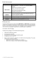
PARTS AVAILABLE Part number Description Viconics BACnet™™ over MS-TP & IP wireless gateway.
Material and Tools Required The following tools and supplies may be required for installation: DIN rail, type NS35/7.5 (35mm x 7.5mm), recommended for panel mount installation. Length of DIN rail should be minimum 6.5 “(165 mm). If using a VWG-PS-DC power supply, use UL listed, Class 2, 24VAC transformer, supplying a minimum of 5VA to the VWG. Note that the VWG-PS-DC power supply provides isolation — a dedicated transformer is not required.
Static Discharge Precautions Static charges produce voltages high enough to damage electronic components. The microprocessors and associated circuitry within a VWG controller are sensitive to static discharge. Follow these precautions when installing, servicing, or operating the system: Work in a static-free area. Discharge any static electricity you may have accumulated. Discharge static electricity by touching a known, securely grounded object.
MOUNTING Mount the VWG in a location that allows clearance for wiring, servicing, and antenna removal. Environmental Requirements Note the following requirements for the VWG mounting location: This product is intended for indoor use only. Do not expose the unit to ambient conditions outside of the range of 0ºC (32º F) to 50ºC (122º F) and relative humidity outside the range 5% to 95% non-condensing (pollution degree 1).
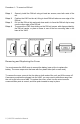
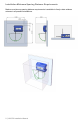
Procedure 1 - To mount on DIN rail Step 1 Step 2 Step 3 Step 4 Securely install the DIN rail using at least two screws, near both ends of the rail. Position the VWG on the rail, tilting to hook DIN rail tabs over one edge of the DIN rail Pull out the DIN rail clip and push down and in to force the DIN rail clip to snap over the other edge of the DIN rail.
Installation Minimum Spacing Distance Requirements Make sure minimum spacing distance requirements is available to freely rotate wireless antenna in all possible orientations.
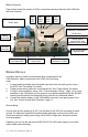
Board Layout Figure below shows the location of LEDs, connections and other features of the VWG with the cover removed.
VWG-PS-AC 120 VAC WALL MOUNTED POWER SUPPLY Both the U.S. and International models of wall power modules are self-contained switching power supplies designed to plug into a standard building power receptacle of appropriate voltage. To supply power to the VWG, you then simply plug the coaxial connector from the VWG-PS-AC into the coaxial power connector on the VWG base board. Power Wiring Only VWG-PS-DC and VWG-PS-AC power supply with factory installed ferrite on the power cord can be used with the VWG.
The packing slip accompanying the VWG will provide the “factory-shipped” IP settings for both NET1 and NET2. Refer to the document LIT-VWG-50-SETUP-Exx for more information for details on the default IP address and how to change it. The supplied ferrite in the VWG packaging needs to be installed on the IP wire in a specific way for FCC compliance. Place IP wire into the provided ferrite as shown in diagram below and make sure to follow the placement dimension. Close and snap the ferrite casing as shown.
RS485-BACnet™ MS-TP wiring. An RS485, optically isolated port uses a 3-position, screw terminal connector and always operates as COM2. Wire to this connector with shielded 8-22 AWG wiring (refer to the TIA/EIA-485 standard). The screw terminals (from left-to-right) are shield, plus (+), and minus (–). The supplied ferrite in the VWG packaging needs to be installed on the MS-TP wire in a specific way for FCC compliance.
ANTENNA INSTALLATION Controller mounted antenna (VWG-WA) All VWG-50 are supplied with a controller-mounted antenna. The antenna is shipped loose in the controller main packaging box. This installation type is to be used only when the controller (and antenna) is not installed inside a closed metal enclosure and that clear reception is expected. Gently screw the antenna into the antenna connector at the top of the VWG. Do not over tight the antenna.
2) Apply Power Apply power to the VWG by plugging in the power plug into either the VWG (if wall mount AC adapter VWG-PS-AC) or the 24VAC-powered VWG-PS-DC module. 3) Check the Status LEDs When power is applied, the green LED labeled “SYS” will light. This is a green LED. Once the VWG boots, the yellow “BEAT” (heartbeat) LED will begin blinking, with a typical rate of about 1 Hz. Boot time should begin within 30 seconds after power is applied.
RELATED DOCUMENTATION For more information on configuring and using the VWG controller, consult the following documents available from the VWG section at www.viconics.
1 x 200ms short blink Power on 2 x 200ms short blinks Power on and card memory initialized properly 3 x 200ms short blinks Power on, card memory initialized properly and serial communication with VWG main board active 4 x 200ms short blinks Power on, card memory initialized properly, serial communication with VWG main board active and wireless networks started successfully 4 x 200ms short blinks and 1 x 1500ms long blink Power on, card memory initialized properly, serial communication with VWG main
Table 4 Standard replacement parts. Part Number Description VWG-BB NiMH Battery Pack (with battery bracket)—see “Replacing the Battery,” Note: Screws used for the VWG are standard #6-3 2 x 3/8" types. Non-replaceable Parts Other than the parts listed in the replacement parts sections, there are no serviceable components on the base assembly. Memory The current release of the VWG limits the maximum number of wireless controllers that can be attached to the VWG40 to 30.
CERTIFICATIONS Federal Communications Commission (FCC) This equipment generates, uses, and radiates radio frequency energy, and if not installed and used in accordance with the instruction manual, may cause interference with radio communications. It has been tested and found to comply with the limits for a computing device pursuant to Part 15 Subpart C of FCC Rules, which are designed to provide reasonable protection against such interference when operated in a commercial environment.
Chassis • Construction: Plastic, din rail or screw mount chassis, plastic cover • Cooling: Internal air convection • Dimensions: 6.313” (16.04 cm) W x 4.820”(12.24 cm) H (including connectors) x 2.438” (6.19 cm) D Environment • Operating temperature range: 0° to 50°C (32°F to 122°F) • Storage Temperature range: 0° to 60°C (32°F to 140°F) • Relative humidity range: 5% to 95%, non-condensing Agency Listings • UL 916, C-UL listed to Canadian Standards Association • (CSA) C22.2 No.