Viconics Zoning System Application Guide VZ7260X5x00W and VZ7656X1000W Controllers VWZS_Rel2_Application_Guide-E02 (R1 Issue Date: January 10th, 2012) 1
Table of Contents: Please refer to the installation manuals of the zoning system controllers for all required information related to wiring, installation, commissioning and integration: • For detailed information on the Viconics VZ72xx Zone controller, please refer and read the VZ72xx Product Guide. Installation and commissioning information is available on document: LIT-VZ7260X-Exx • For detailed information on the Viconics VZ76xx RTU controller, please refer and read the VZ76xx Product Guide.
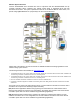
1) System Overview and Architecture The Viconics Zoning System product is comprised of 2 controller types. • The VZ7260X5x00W zoning controller • The VZ7656X1000W RTU / HP controller When combined, they deliver a simple and efficient demand based system implementation which controls pressure dependent VAV zones with roof top units (RTU). The system is designed to work with small to medium sized RTU staged heating and cooling equipment (2 to 20 tons).
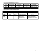
Zone Controllers Available Models & Features: Viconics Part Number Control Outputs PIR Cover VZ7260F5000W VZ7260F5500W VZ7260C5000W 2 x Analog 0 to 10 VDC 1 x Auxiliary reheat contact PIR cover ready.
Wireless System Overview Viconics VZ72605x00W zone controllers are used in conjunction with the VZ7656X1000W roof top controller controllers. When combined, they operate typical single or multistage RTUs and their associated local zones. The system operates the same as in the BACnet MS-TP wired version, but operate using ZigBee/IEEE 802.15.4 physical layer for the communication bus.
1A) Initial Design Criteria Considerations The scope of this document is not intended to be a resource or white paper on VAV zoning system design. There are many good resources available on the subject of VAV zoning systems and their associated advantages and disadvantages. Please consult these resources for further information on this subject.
(NS) Networked Systems operation. There is a high-level supervisory device installed and used in this configuration. In this application, a Viconics VWG and Jace-driver are the network coordinators for all controllers associated to the system and reporting their data point values. Each VZ76xx RTU controller and its associated VZ72xx zone controllers will use the same PAN ID and channel as the Viconics VWG and Jace-driver. The range of PAN ID on all controllers to use is 1 to 250.
1D) Special Considerations A typical office installation may require that a single unit service areas being used for different applications. These areas will commonly be a combination of external and internal zones. It is always good to verify the intended use of all areas knowing their true peak loads before committing to its final design and sizing. It may be necessary to oversize or undersize the design to meet their daily demands.
2) Zone Controllers VZ7260X5x00W Operation The following information needs to be carefully read and properly understood if proper system commissioning is to be achieved. Contrary to low end commercial and residential zoning controllers which use a two positions open-close actuator, Viconics VZ7260X5x00X uses proportional analog 0 to 10 VDC modulating damper actuator. This enables performances and control sequences to be much closer to what is normally found in DDC application specific control devices.
2A) Demand Based Heating and Cooling System System operation as a whole consists of selecting which zone controllers will have heating and cooling weighted votes used by the RTU controller to which they are attached. The weighted heating and cooling demand values from the selected master zones are then used by the RTU controller to determine if heating or cooling action is required for the system as a whole. Both internal and external zones are typically serviced by the same unit.
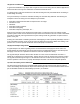
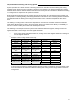
Example 2 with 3 voting master zones only Voting Zone 1 Current heat demand 100% Heat weight set 100% Resulting heat weight to RTU 100% Current cool demand 0% Cool weight set 100% Resulting cool weight to RTU 0% Voting Zone 2 Current heat demand 0% Heat weight set 100% Resulting heat weight to RTU 0% Current cool demand 100% Cool weight set 75% Resulting cool weight to RTU 75% Voting Zone 3 Current heat demand 0% Heat weight set 100% Resulting heat weight to RTU 0% Current cool demand 100% Cool weight set
2B) Overrides and User Zone Interface Lockouts Each zone controller can have a function locked out for the local user. This can prevent unwanted inputs to the system as a whole when the zone controllers are installed in public areas or when certain local user interface functions of the zone controllers are to be prevented. Lock level is access through the lockout configuration parameter. Please set the appropriate level for each individual zone in the system according to their requirements.
2D) Heating and Cooling Weight Zone Selection For any system to properly operate, care must be taken to select which zones will be driving the system and their weight attached to the calculations. The values below are provided as an initial rule of thumb and need to be re-evaluated on a job per job basis depending on the specifics of the system design and layout.
o External zones considered of primary importance should have both their heating and cooling weight set to 100% o Zones considered of secondary importance can have their weight set to a lesser value than 100% to reflect their importance on the systems total voting when making demand calculations. o Due to, their location, exposure, design, etc……, certain zones can have problematic behaviour specifically in peak heating or cooling mode. (Ex.: when an office surrounded by panoramic windows).
Maximum Heatflow Adjustment (MaxHTPos) Many installers will assume that this parameter sets the Maximum airflow of the VAV damper when the RTU is delivering hot air. This is not the case. Both the maximum amount of cold AND hot air delivered to the zone is set by the (Max Pos) zone damper parameter. Please see section above for more details.
How To Test and Balance the Minimum, Maximum and Heat Flow Values: Balancing Minimum Air Flow 1. Be sure local system heating is allowed by setting the outdoor heating lockout value at the RTU controller (H Lock) 2. Be sure the system is currently in heating mode. As viewed locally at the RTU controller by pressing the manual scroll button and displaying the local Zone Sequence = Heat message prompt. 3.
- The damper position is never linear or proportional to airflow in a pressure dependent application. Depending on how the zone damper was sized, a box may best slightly oversized, or slightly undersized. In all cases, the PI loop (Proportional Integral) of the zone controller will always compensate to find the proper required position to satisfy the current zone demand.
2G) Passive Infra Red Motion Detector Cover (PIR) The Viconics zone controllers are compatible with the new Viconics PIR (Passive Infra Red) cover accessory. Controllers equipped with a PIR cover provide advanced active occupancy logic, which can automatically switch occupancy levels from occupied to stand-by as required when local activity is detected in the room. This advanced occupancy functionality provides advantageous energy savings during occupied hours without sacrificing occupant comfort.
2 H) AI4 CO2 / Other Sensor Input Operation AI4 CO2 Sensor Input Operation The VT76XXE controller features a 0-10VDC input (AI4) that is used for monitoring using any 0-10VDC sensor or to control the building CO2level. Using any 0-10VDC value for monitoring If the AI4 input is used for monitoring purposes only (even if monitoring CO2 with a CO2 sensor), the AI4 parameter should be set to None (not CO2).
2 I) Disable Minimum Position parameter The VZ7260 zone controllers feature the DisMinPo (Disable Minimum Position) parameter that is used to enable/disable the minimum damper’s minimum position parameter setting if the zone sequence (heat/cool) is different than the controller’s demand (heat/cool). The goal of this parameter is to prevent overcooling or overheating of zones that have demands that differ from the general zone sequence due to the airflow through the damper opening (at the minimum position).
3) RTU Controllers VZ7656X1000W Operation The following information needs to be carefully read and properly understood if proper system commissioning is to be achieved. Unlike low end commercial or residential zoning controllers which typically only use two position demand or non- demand logic to initialize heating and cooling functions, Viconics VZ7656X1000X uses local PI zone demand(s) to operate heating and cooling stages.
Many configuration and normal operation factors can limit action to the heating and cooling stages.
3D) RTU Heating and Cooling Supply Air Temperature Lockouts One problematic aspect of any VAV zoning system is high demand for (heating or cooling) when most of the zone VAV dampers are closed. This leads to most of the supply air being re-circulated through the pressure by-pass and can lead to extremely hot or cold supply temperature. - To prevent high supply temperatures (specifically with gas heating RTU), adjust discharge air temperature high limit to required value.
3F) Critical Mid-Season Changeover Heating and cooling RTU equipment cycling during mid-seasons is inevitable with a zoning VAV system if any degree of comfort is to be maintained. A properly setup system will be able to deliver comfort to conflicting zone demands during the mid-season period by alternating heating and cooling at the RTU.
By-Pass Damper Operation: - Control signal = 0 VDC = Static pressure by-pass damper fully closed = No air recirculation from supply to return Control signal = 10 VDC = Static pressure by-pass damper fully opened = Maximum air recirculation from supply to return When the fan output is off (Terminal G), the static pressure control loop is off and the by-pass damper is fully opened to 10 VDC output. This will minimize the air pressure related noise during initial fan start-up.
3I) Indoor Air Quality Control & Operation The fresh air damper can be controlled through more than one sequence to achieve different control strategies such as free cooling (economizer mode), minimum fresh air control and CO2 level control. Here are the control sequences available: Note: For the sequences mentioned below, the following conditions must be met in order for the sequences to be performed as stated: - Max Pos parameter value must be greater than Min Pos Parameter value.
Economizer Mode and Fresh Air Measurement Station If the fresh air damper is to be used for both free cooling and minimum fresh air volume control (economizer mode and fresh air measurement station, but without CO2 level control), only the Min FA parameter and the free cooling sequence will be active. - The FA Range parameter should be set to a value higher than 0 CFM (0 CFM disables the fresh air control). Min FA (minimum fresh air) parameter should be set to the desired level.
Economizer Mode and CO2 Level Control If the fresh air damper is to be used for both free cooling and CO2level control (economizer mode and CO2 level control, but without fresh air measurement station), only the Min Pos, Max Pos, Min CO2and Max CO2 parameters as well as the free cooling sequence will be active. - The FA Range parameter should be set to 0 CFM.
Economizer Mode, CO2 Level Control and Fresh Air Measurement Station If the fresh air damper is to be used for both free cooling and CO2 level control with a fresh air measurement station, only the Min FA, Max FA, Min CO2 and Max CO2 parameters as well as the free cooling sequence will be active. - The FA Range parameter should be set to something other than 0 CFM.
4) Wireless Communication Overview The Viconics VZ7260X5x00W and VZ7656X1000W controllers, Viconics Wireless Gateway (VWG) and Jace-driver and other related wireless controller family (VT7xxxXxxxxW) networkable devices operate using ZigBee/IEEE 802.15.4 physical layer for communication. General characteristics of the wireless physical communication layer are: · · · · · Wireless physical layer of 2.
4A) (SA) Stand-Alone applications When PAN ID is used with a range of 251 to 500, for (SA) Stand-Alone Systems. In this application, the VZ76xx controller(s) act as the coordinators to their own system. I.E. they are the network masters for each VZ72xx controller reporting to them when the whole zoning system(s) is self sufficient and communication and no external communication is required.
4B) (NS) Networked System applications When PAN ID is used with a range of 1 to 250, for (NS) Networked Systems. In this application, any controller(s) are simply routers to the system. The VWG and Jace-driver is the coordinators to the system. The VWG and Jace-driver are the network masters for any controller(s) reporting to them, where zoning system(s) are required to communicate and exchange data points with the Viconics VWG and Jace-driver set.
4C) Basic Initial Design and Deployment Considerations Proper design considerations need to be addressed prior to the installation of a Viconics wireless zoning system. 1. To avoid network interference with 802.11 Wi-Fi devices in the 2.4GHz spectrum range, Viconics recommends the use of 802.15.4 channels 15, 25 and 26 only. 802.11 Wi-Fi transmissions overlap and may interfere with other channel selections allowed by 802.15.4 (Channels 11 to 14 & 16 to 24) 2.
3. Ensure that the minimum distance between any Viconics node and any Wi-Fi devices (wireless routers, wireless adapters, lap-tops using wireless networks, etc….) to be at least 3 feet (1 M) and preferably 10 feet (3 M) or more. Minimum 3 feet (1 M) between Wi-Fi equipment and Viconics wireless devices Preferably 10 feet (3 M) or more between Wi-Fi equipment and Viconics wireless devices 4.
4D) Communication status LED and Troubleshooting Each controller has a communication status service LED for troubleshooting purposes. Monitoring this LED will determine the network condition for each individual device and will tell you if they are successfully communicating with their peers on the network. VZ76xx Adapter LED Status Indicators (SA) Stand-Alone applications.
VZ72 Adapter LED Status Indicators 1 x 200ms short blink 2 x 200ms short blinks 3 x 200ms short blinks 4 x 200ms short blinks 4 x 200ms short blinks and 1 x 1500ms long blink 4 x 200ms short blinks and 1 x 1500ms long blink and 1 x 3000ms long blink Power on Power on Communicating with controller base Power on Communicating with controller There is connectivity to wireless network Power on Communicating with controller There is connectivity to wireless network VZ76 or VWG / Jace-Driver is communicating wi
5B) Proper Commissioning RTU Controllers At the RTU level, care should be applied to insure the following conditions are met: - Proper sizing of the RTU heating and cooling capacity to insure it will meet the highest instantaneous peak loads of the areas deserved by the system. - Proper strategy and system layout of the mechanical system architecture. - Proper commissioning and verification of the by-pass system.
RTU Commissioning RTU mechanical cooling functional verification done Maximum Delta temperature ( return to supply temp ) for cooling stage #1: Maximum Delta temperature ( return to supply temp ) for cooling stage #1 & 2: Economizer cooling functional verification done Minimum position of economizer properly set? RTU controller Aux output used to disable minimum position of economizer check ? RTU heating functional verification done Maximum Delta temperature ( return to supply temp ) for heating stage #1: M
Zone Number ( ) Commissioning VAV damper actuator properly rigged and verified? ( opens and closes with demand ) Proper adjustments of zone side take off balancing damper? Proper balancing of zone minimum position? CFM = Proper balancing of zone maximum position? CFM = Proper balancing of zone MaxHeatflow position? (If reheat is used) CFM = Verification of Reheat (If reheat is used) Maximum Delta temperature of Reheat (If duct reheat is used) Important configuration property set ? - Zone MAC: - PAN ID - Cha
6B) Critical Point Checks To insure proper and reliable operation of the system, it is the responsibility of the system designer or installer to properly verify all important milestones of the project. This includes all other contractual aspects for the system performed outside of the control system scope of work: - Design phase: load calculations and ductwork layout and sizing, equipment selection, etc…..