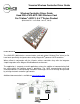
Viconics Wireless Controller Driver Guide Wireless Controller Driver Guide Used With VWG-APP-1000 Wireless Card For Tridium® JACE 2, 6 & 7® Series Product (028-6018 R4 Issue Date: June 5h, 2012) Product Overview The VWG-APP-1000 wireless communication card and related “WirelessTstat” driver jar file have been specifically designed to be used by Niagara AX® powered JACE controllers.
Compatibility & History Revision Table Release 1, May 2009 Associated Jar Files Revision Level Associated Displayed Driver Name WirelessStat.jar 3.1.30 Main 2.1 2.1.1 2.1.
Trademarks Niagara, Niagara AX is a registered trademark of Tridium, Inc. Disclaimers NO WARRANTY. Viconics, Inc. (herein after referred to as “Viconics”) makes no warranty as to the accuracy of or use of this technical documentation. Any use of the technical documentation or the information contained therein is solely at the risk of the user. Documentation may include technical or other inaccuracies or typographical errors.
THIS DEVICE COMPLIES WITH PART 15 OF THE FCC RULES. OPERATION IS SUBJECT TO THE FOLLOWING TWO CONDITIONS: (1) THIS DEVICE MAY NOT CAUSE HARMFUL INTERFERENCE, AND (2) THIS DEVICE MUST ACCEPT ANY INTERFERENCE RECEIVED, INCLUDING INTERFERENCE THAT MAY CAUSE UNDESIRED OPERATION.
About Viconics Wireless Mesh Networks The Viconics wireless card (VWG-APP-1000) and related network able wireless controllers series operate using ZigBee/IEEE 802.15.4 physical layer for communication. General characteristics of the wireless physical communication layer are: Uses a wireless physical layer of 2.
Only use Com1 option slot card position for the card 6
Basic Initial Design and Deployment Consideration IMPORTANT: It is HIGHLY recommended that you do a proper field survey with the Viconics survey tools to establish connectivity limitations and architecture layout on ALL job sites considered for deployment with the Viconics wireless controller products. Please refer to the following manual for the survey procedures and tool usage: MAN VWG-SURVEY-Exx. Please note that the following is well covered in the field survey tool procedure manual.
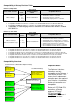
Any given device / node / controller including the Jace –coordinator can ONLY give a maximum 6 ZigBee addresses out to other devices so they join the active ZigBee network. This means for any device / node / controller to be able to successfully join a ZigBee network, it needs an address to be assigned by another device / node / controller which is within connectivity and that has NOT already assigned its maximum of 6 addresses allowed.
Orphan Nodes. As such it is important to understand that HOW the network is first initially started up “may” create orphan unassigned devices / nodes / controllers that will seem to NOT want to join the ZigBee network. Let’s first understand how an orphan node is created. A typical example is when jobs are started on a technician desk before sending the devices / nodes / controllers in the field for installation.
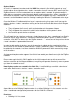
Yellow device / node / controller have given out its 6 addresses to other devices in building A. Building B devices / nodes / controllers can only be connected through blue device / nodes / controller due to maximum distance coverage. Result: Orange devices / nodes / controllers cannot join the ZigBee network.
5H stands for 5 hops maximum recommended. 5H is for a simple process when laying out the architecture of the network. ANY given device / node / controller should be “optimized” to be NO FURTHER IF POSSIBLE than 5 Hops to & from the Jace / Coordinator. This is due to the nature of the Viconics ZigBee stack in the wireless controllers.
Proper design considerations need to be addressed prior to any installation of a JACE with a Viconics wireless communication card and related wireless controllers. Viconics recommends using a per floor horizontal architecture vs. a vertical one. Transmitting from one floor to the other may be possible in certain applications (such as going through stair ways), but the design and optimization of the controller antenna is designed for optimal horizontal distance penetration and not a vertical one.
Non line of sight distance for typical gypsum wall partitions made with metal stud frame should be under 30 feet ( 10M ) 3. Ensure that the minimum distance between any Viconics node and any Wi-Fi devices (wireless routers, wireless adapters, lap-tops using wireless networks, etc….) to be at least 3 foot (1 M) and preferably 10 feet (3 M) or more.
4. Ensure that at least one controller is within 30 feet of the VWG for every cluster of 10 controllers installed. 5. Always try to locate if possible the VWG near the center of all associated wireless controllers. 6. Always try to locate the VWG near on in line of sigh to as many wireless controllers as possible. 7. Try to avoid metal, brick walls or concrete obstructions between wireless devices as much as possible. 8. Make sure the antenna on the VWG is always perpendicular to the floor. 9.
50 feet (15 M) 16
JACE and Wireless Communication Card Configuration Initial Configuration Note: The following instructions assume you are familiar with the AX workbench environment and its related functions: Install the wireless communication card as stipulated by the instructions provided with the wireless card Copy the “WirelessTstatNetwork” and “WirelessTstatDevices” jar files to your local AX Workbench module folder Using the Software Manager, add the “WirelessTstat” jar file to the target JACE with the wirel
Right hand click the “WirelessTstatNetwork” driver to load the network property sheet Under the Serial Port Configuration, set Port Name to “COM1”. Only COM1 can be used with the wireless communication card since hardware flow control is required. All other properties are locked and set as read only Set the ZigBee wireless communication card options.
VWG ZigBee Settings Those settings are where you set the ZigBee PAN ID (Personal Area Network Identification) address and the channel for the wireless communication card. Gateway ZigBee PAN ID. (Personal Area Network Identification). This is where the PAN ID of the gateway is set. Range is from address 1 to 500. The default of “0” is not a valid PAN ID. Channel Select. This is where the current Channel frequency used by the gateway is set. Range is from 11 to 26.
When properly configured, the issue of RF interference and lost data between the JaceDriver and the controllers can be avoided. Without proper care or proper software configuration serious interference issues can happen. Again, Viconics recommends using only channels 15 & 25. Viconics recommends this purely as a practical tip for deployment in the field based on our experience. These channels are not affected and are out of the range of IEEE802.11x Wi-Fi Channels spectrum.
Controller Discovery & Database Tools IMPORTANT NOTE (Please Read Carefully): The communication layer operates differently than “most” low level traditional wired communication bus. The “heart” of the network resides on the wireless communication card found on the JACE. It is commonly referred to as the “coordinator” to the network.
FOR MORE INFORMATION ON THE DISCOVERY PROCESS & GENERAL SYSTEM ARCHITECTURE, please refer to the survey tool manual which provides more information on the subject: Rx_MAN VST5000W5000W-Exx. Name. The controller’s given name in the database. The name is constructed of the controller model number and its current local MAC address. Ex. A VT7300C5000W with a local MAC address of 21 will carry a name in the database of VT7300C5000_21. The model name text string is fully editable as required. Model.
Status. Indicates if the current controller is online to the JACE or not. o If online, the status will be {OK} and the controller line will be white o If offline, the status will be {down} and the controller line will be yellow Health. The current status of each controller wireless node. “OK” is for an online controller and the date and time represent the last time a communication event was received by the JACE from a controller.
Then select the required controller model number that will be installed on the job site. Remember to select ALL controllers if more than one is required. The controller can be enabled now or at a later date if the installation is done in segments.
Edit. Allows you to edit the characteristics assigned to any specific wireless controller. The controller name, Com Address and enabled flag can be modified. The controller Model Type cannot be changed. If another model is required under the same address, simply delete it and either create a new one offline or re-discover the proper one. Match.
Status: Will give the sanity of the wireless controller to the network o (ok) Device heartbeat reporting properly with no fault encountered o (down) Device heartbeat failed. No communication to the device o (fault) Transaction time out on specific object write(s). Device heartbeat is still valid o (disabled, fault) Device has been disabled Enabled: Enables or disables the communication to the wireless controller.
Device Info, Address Info & Communication Module Info: All read only properties related to the local controller and are given as general information. Wireless Signal Info: CRSS - Coordinator Receiving Signal Strength (in %) TRSS - Controller Receiving Signal Strength (in %) These values can be known before implementing the Viconics wireless system by using the Viconics Survey Tool (VST5000W5000W). It will determine if the area is suitable for using Viconics wireless products.
It is safe to assume that if more advanced functions and services are added to the station, the available resources for the driver will be less. It is important that once the station is all done and installed with all GUI, services, trends, logs, etc…that resources are monitored and not above what is recommended by Tridium for each specific type of JACE platform. All objects such as GUI’s, configuration parameters and statuses will be discovered when a discovery process is done.
VT7200C5x00W VT7200F5x00W VT7300A5x00W VT7305A5x00W VT7300C5x00W VT7305C5x00W VT7350C5x00W VT7355C5x00W VT7300F5x00W VT7305F5x00W VT7350F5x00W VT7355F5x00W Objects Supported By Models: (VT7200 & VT7300 Series) Please refer to the specific installation guide of each VT7200 & VT7300 controllers for a detailed overview on each property listed Room Temperature Numeric Writable Present Value (R,W) Outdoor Temperature Numeric Writable Present Value
VT7200C5x00W VT7200F5x00W VT7300A5x00W VT7305A5x00W VT7300C5x00W VT7305C5x00W VT7350C5x00W VT7355C5x00W VT7300F5x00W VT7305F5x00W VT7350F5x00W VT7355F5x00W Aux Command Boolean Writable Present Value (R,W) Password Numeric Writable Present Value (R,W) PI Heating Demand Numeric Point Present Value (R) PI Cooling Demand Numeric Point Present Valu
VT7200C5x00W VT7200F5x00W VT7300A5x00W VT7305A5x00W VT7300C5x00W VT7305C5x00W VT7350C5x00W VT7355C5x00W VT7300F5x00W VT7305F5x00W VT7350F5x00W VT7355F5x00W Room Temperature Override Boolean Writable Present Value (R,W) Configuration Setpoint Type Boolean Writable Present Value (R,W) Outdoor Temperature Override Boolean Writable Present Value (R,W)
Object Type Object Property VT7600A5x00W VT7652A5x00W VT7600B5x00W VT7652B5x00W VT7600F5x00W VT7652F5x00W VT7606E5x00W VT7656E5x00W VT7605B5x00W VT7656B5x00W VT7607B5x00W VT7657B5x00W VT7600H5x00W VT7652H5x00W VT7600W5x00W VT7652W5x00W Objects Supported By Model (VT7600 Series) Please refer to the specific installation guide of each VT7600 controllers for a detailed overview on each property listed Room Temperature Numeric Writable Present Value (R,W)
VT7600A5x00W VT7652A5x00W VT7600B5x00W VT7652B5x00W VT7600F5x00W VT7652F5x00W VT7606E5x00W VT7656E5x00W VT7605B5x00W VT7656B5x00W VT7607B5x00W VT7657B5x00W VT7600H5x00W VT7652H5x00W VT7600W5x00W VT7652W5x00W PI Cooling Demand Numeric Point Present Value (R) PI Heating Demand Numeric Point Present Value (R) Enum Writable Present Value (R,W)
Present Value (R) Numeric Writable Present Value (R,W) Numeric Writable Present Value (R,W) Boolean Writable Present Value (R,W) Heating Setpoint Limit Numeric Writable Present Value (R,W) Cooling Setpoint Limit Numeric Writable Present Value (R,W) Numeric Point Present Value (R) Dehumidification Lockout Functions Economizer Output G Fan Status Reversing Valve Status Aux Status PIR Motion Status PIR Motion Status Boolean Point Present Value (R) Boolean Point Present Value (R) Boolean Po
High Temperature Reset RH Setpoint Numeric Writable Present Value (R,W) Present Value (R,W) VT7605B5x00W VT7656B5x00W VT7652W5x00W Numeric Writable VT7656E5x00W Present Value (R,W) VT7606E5x00W Numeric Writable VT7652F5x00W Present Value (R,W) VT7600F5x00W Numeric Wr
VT7652H5x00W VT7600W5x00W VT7652W5x00W VT7600H5x00W VT7657B5x00W VT7607B5x00W VT7656B5x00W VT7605B5x00W VT7656E5x00W VT7606E5x00W VT7652F5x00W VT7600F5x00W VT7652B5x00W Present Value (R,W) VT7600B5x00W Enum Writable Object Property VT7652A5x00W Cooling Stages Object Type VT7600A5x00W Object Name Enum Writable Present Value (R,W)
Fresh Air Alarm High CO2 Alarm Economizer Maximum Position TRSS VT7600H5x00W VT7652H5x00W VT7600W5x00W VT7652W5x00W Compressor Auxiliary Lockout VT7657B5x00W Reversing Valve Config VT7607B5x00W Comfort Mode VT7656B5x00W Low Balance Point VT7605B5x00W High Balance Point VT7656E5x00W Mixed Air Setpoint VT7606E5x00W Mechanical Cooling Enable VT7652F5x00W Economizer Minimum Position VT7600F5x00W Economizer Changeover Setpoint VT7652B5x00W Heatpump Stages VT7600B5x00W Fan Control VT7652
Fresh Air Level Supply Heat Lockout Status CO2 Level Discharge Air Alarm Heating Stages Fresh Air Max Range Discharge High Limit Setpoint VT7652F5x00W VT7600F5x00W VT7652B5x00W VT7600B5x00W VT7652A5x00W VT7652W5x00W Analog Heat Output Status VT7600W5x00W AI1 Value VT7652H5x0
Analog Heat Output Status Supply Heat Lockout Status Discharge Air Alarm Discharge High Limit Setpoint Discharge Low Limit Setpoint Minimum Supply Heat Setpoint Supply Heat Lockout Temperature Supply PI Heat Demand Present Value (R,W) Numeric Writable Present Value (R,W) Numeric Point Present Value (R) Numeric Writable Present Value (R,W) Numeric Writable Present Value (R,W) Numeric Writable Present Value (R,W) Numeric Writable Present Value (R,W) Numeri
Objects Supported By Models: (VTR7300 Controllers & VRP5000W Wireless Repeater) Please refer to the specific installation guide of each controller for a detailed overview on each property listed VTR7300A5x00W VTR7305A5x00W VTR7350A5x00W VTR7355A5x00W Wireless Repeater The wireless repeater (VRP5000W1000W) has been specifically designed to be used within a Viconics wireless ZigBee network.
VTR7300A5x00W VTR7305A5x00W VTR7350A5x00W VTR7355A5x00W System Mode Enum Writable Present Value (R,W) Fan Mode Enum Writable Present Value (R,W) Keypad Lockout Enum Writable Present Value (R,W) Dehumidification Lockout Boolean Writable Present Value (R,W) Password Numeric Writable Present Value (R,W) PI Heating Demand Numeric Point Present Value ® PI Cooling Demand Numeric Point Present Valu
VTR7300A5x00W VTR7305A5x00W VTR7350A5x00W VTR7355A5x00W Temporary Occupancy Time Enum Writable Present Value (R,W) Get From Numeric Writable Present Value (R,W) Deadband Numeric Writable Present Value (R,W) Heating Setpoint Limit Numeric Writable Present Value (R,W) Cooling Setpoint Limit Numeric Writable Present Value (R,W) Display Scale Boolean Writable Present Value (R,W) Menu Scroll Boo
VTR7300A5x00W VTR7305A5x00W VTR7350A5x00W VTR7355A5x00W Auto Mode Enable Boolean Writable Present Value (R,W) Pipe Number Enum Writable Present Value (R,W) Fan Mode Sequence Enum Writable Present Value (R,W) Setpoint Function Boolean Writable Present Value (R,W) Proportional Band Enum Writable Present Value (R,W) Auto Fan Boolean Writable Present Value (R,W) Stand-By Time Numeric Writable
VTR7300A5x00W VTR7305A5x00W VTR7350A5x00W VTR7355A5x00W Cool No/Nc Boolean Writable Present Value (R,W) Pulsed Heat Boolean Writable Present Value (R,W) Low Battery Alarm Boolean Point Present Value (R) Wireless Window Switch Used Boolean Point Present Value (R) Wireless Window Switch Status Boolean Point Present Value (R) Wireless Door Switch Used Boolean Point Present Value (R) Wireless Do
Objects Supported By Models: (VZ7000 Zoning Products) Object Type Object Property VZ7200F5x00W VZ7260F5x00W VZ7260C5x00W VZ7656B1000W VZ7656R1000W VZ7656H1000W VZ7656F1000W VZ7656E1000W Please refer to the specific installation guide of each controller for a detailed overview on each property listed.
PI Heat Weight VZ7656E1000W Present Value (R,W) VZ7656F1000W Enum Writable VZ7656H1000W VZ7260C5x00W Present Value (R) Object Property VZ7656R1000W VZ7260F5x00W Numeric Point Object Type VZ7656B1000W VZ7200F5x00W Weighted PI Heating Demand Object Name PI Cool Weight BI1 Status Enum Writable Present Value (R,W) Boolean Point Present Value (R) UI3 Status Boolean Point Present Value (R)
Damper Position Numeric Point Present Value (R) Config Motion Detection Boolean Writable Present Value (R,W) VZ7656E1000W AO2 RA/DA VZ7656F1000W VZ7656H1000W Present Value (R,W) VZ7656R1000W Present Value (R) Boolean Writable Object Property VZ7656B1000W VZ7260F5x00W Boolean Point Object Type VZ7260C5x00W VZ7200F5x00W AO2 Lock Status Object Name Reheat C
VZ7200F5x00W VZ7260F5x00W VZ7260C5x00W VZ7656B1000W VZ7656R1000W VZ7656H1000W VZ7656F1000W VZ7656E1000W Highest PI Cool Zone Mac Numeric Point Present Value (R) Highest PI Heat Demand Numeric Point Present Value (R) Present Value (R) Present Value (R) Object Name Highest PI Cool Demand Y1 Status Object Type Numeric Point Boolean Point Ob
VZ7200F5x00W VZ7260F5x00W VZ7260C5x00W VZ7656B1000W VZ7656R1000W VZ7656H1000W VZ7656F1000W VZ7656E1000W Anticycle Enum Writable Present Value (R,W) Event Display Enum Writable Present Value (R,W) Get From Numeric Writable Present Value (R,W) Deadband Numeric Writable Present Value (R,W) BI1 Status Present Value (R) Boolean Point BI1 Config Enum Writable
VZ7656B1000W VZ7656R1000W System Mode HP Zoning Enum Writable Present Value (R,W) Emergency Heat Mode Boolean Writable Present Value (R,W) Minimum Supply Heat Setpoint Numeric Writable Present Value (R,W) Boolean Writable Present Value (R,W) VZ7656E1000W VZ7260C5x00W Present Value (R,W) Object Property VZ7656F1000W VZ7260F5x00W Boolean Writable Reversing Valve Config Object Type VZ7656H1000W VZ7200F5x00W Compress
List of Property Numeric Value Range Restrictions Please refer to the specific installation guide of each controller for a detailed overview on each property listed Object Name AI1 Value Analog Heat Output Status AO2 Outside Air Lockout Setpoint AO2 Status BO5 Outside Air Lockout Setpoint ByPass Damper Position ByPass Damper Position Or VFD CO2 Level Cooling Demand Limit Cooling Lockout Temperature Cooling Setpoint Limit Damper Max Heat Position Damper Maximum Position Damper Minimum Position Damper Posit
Object Name Minimum Supply Heat Setpoint Mixed Air Setpoint Occupied Cooling Setpoint Occupied Heating Setpoint Outdoor Temperature Outdoor Temperature Password PI Cooling Demand PI Heating Demand Powerup Delay Return Air Temperature Room Humidity Room Humidity Room Temperature RTC Comm Address Standby Cooling Setpoint Standby Heating Setpoint Standby Time Static Pressure Static Pressure Setpoint Supply Heat Lockout Temperature Supply PI Heat Demand Supply RH Supply Temperature Supply Temperature Unoccupie
List of Property Enumeration Sets for BV Objects Please refer to the specific installation guide of each controller for a detailed overview on each property listed Object Name Object Type Thermostat Range / Indexes AI1 Configuration AO2 Lock Status AO2 RA/DA Auto Fan Auto Mode Enable Aux Command Aux Contact Aux Status BI1 Status BI2 Status BO5 Contact Function BO5 Lock Status BO5 Status BO5 Time Base Comfort Mode Compressor Auxiliary Lockout Config Motion Detection Control Type Cool NO/NC Cool Stages Lo
Object Name Low Battery Alarm Mechanical Cooling Enable Menu Scroll Outdoor Temperature Override PIR Motion Status Progressive Recovery RBI2 Status Reheat Time Base Reversing Valve Config Reversing Valve Status RH Display Room Humidity Override Room Temperature Override RTC Smart Recovery Active RUI1 Status Service Alarm Set Clock Alarm Setpoint Function Setpoint Type Supply Heat Lockout Status Supply Heat Lockout Status UI3 Status Units W1 Status W2 Status Window Alarm Wireless Door Switch Status Wireless
List of Property Enumeration Sets for MV Objects Object Alarm ( VT72xx & VT73xx ) Alarm-VT76xx Index 1 2 3 4 5 6 7 1 2 3 4 5 6 7 8 9 10 11 12 13 14 15 16 Range Restrictions No alarm Window alarm Filter alarm Service alarm Window & filter alarms Window & service alarms Filter & service alarms No alarm Frost alarm Clock alarm Clock & frost alarms Filter alarm Filter & frost alarms Filter & clock alarms Filter & frost & clock alarms Service alarms Service & frost alarms Service & clock alarms Service & fr
Object Aux Configuration Cooling CPH Control Type BI1 Config ( VT72 / VT73xx ) BI2 Config ( VT72 / VT73xx ) DI1 Config ( VT76xx ) DI2 Config ( VT76xx ) Index 1 2 3 4 5 6 1 2 1 2 3 1 2 3 4 5 1 2 3 4 5 1 2 3 4 5 6 1 2 3 4 5 6 Range Restrictions Not Used Normally Opened With Occupancy Normally Closed With Occupancy Normally Opened With Occupancy & Fan Normally Closed With Occupancy & Fan Network Controlled 3 CPH 4 CPH Highest Average of 3 highest Average of 5 highest None Rem NSB Motion NO Motion NC Wi
Object BI1 Config ( VZ7200X ) Effective Occupancy Door Time Fan Mode ( VT73xx ) Note 4: Fan Mode ( VT76xx ) Note 4: Fan Mode Sequence (VT73xx) Note 4: Fan Status (VT73xx ) Fan Control Index 1 2 3 1 2 3 4 1 2 3 4 5 6 7 8 9 10 1 2 3 4 5 1 2 3 1 2 3 4 5 1 2 3 4 1 2 3 Range Restrictions None Motion NO Motion NC Occupied Unoccupied Temporary Occupied Stand-by 1 minute 2 minutes 3 minutes 4 minutes 5 minutes 6 minutes 7 minutes 8 minutes 9 minutes 10 minutes Low Med High Auto On On Auto Smart Low - Med -
Object Floating Motor Timing Heat Pump Stage Heating CPH Cooling Valve Status Heating Valve Status Keypad Lockout ( VT73xx ) Keypad Lockout ( VT72xx ) Keypad Lockout ( VT76xx ) Index 1 2 3 4 5 6 7 8 9 10 11 12 13 14 15 16 17 18 1 2 1 2 3 4 5 6 1 2 1 2 3 4 5 6 1 2 3 4 1 2 3 Range Restrictions 0.5 Minutes 1 Minute 1.5 Minutes 2 Minutes 2.5 Minutes 3 Minutes 3.5 Minutes 4 Minutes 4.5 Minutes 5 Minutes 5.5 Minutes 6 Minutes 6.5 Minutes 7 Minutes 7.5 Minutes 8 Minutes 8.
Object Minimum On/Off Time ( Anticycle ) Event Display Heating Stages Cooling Stages Network Handle Occupancy Command On Off Control CPH Output #1 Configuration ( VT72xx ) PI Cooling Weight PI Heating Weight Pipe Number Proportional Band ( VT76xx ) Index 1 2 3 4 5 6 1 2 1 2 1 2 3 1 2 3 1 2 3 4 5 6 1 2 1 2 3 4 5 1 2 1 2 3 4 5 6 7 8 Range Restrictions 0 Minutes 1 Minute 2 Minutes 3 Minutes 4 Minutes 5 Minutes 2 Events 4 Events 1 Stage 2 Stages Default Zone Handle Default Minus Occupancy Full Release
Object Proportional Band-( VT72xx & VT73xx ) Pulsed Heat RUI1 Config Index 1 2 3 4 5 6 7 1 2 3 1 2 3 4 5 RBI2 Config Reheat Config 6 1 2 3 1 2 3 4 5 Reheat CPH Zone Sequence Sequence Of Operation ( VT73xx & VT72xx ) Note 2 1 2 3 4 5 6 7 1 2 1 2 3 4 5 6 Range Restrictions 2 ºF / 1.1 ºC 3 ºF / 1.7 ºC 4 ºF / 2.2 ºC 5 ºF / 2.8 ºC 6 ºF / 3.3 ºC 7 ºF / 3.9 ºC 8 ºF / 4.4 ºC On Off Occupancy Output None Filter Service (COC/NH) Change over dry contact. Normally Heat (COC/NC) Change over dry contact.
Object Sequence Of Operation (VTR73xx) Note 3 Static Pressure Range System Mode-VT76Hxx System Mode – VT76xx System Mode – VZ72xx, VT72xx & VT73xx Note 1, Note 2 & Note 3 Temporary Occupancy Time ( VT76xx ) Index Range Restrictions 1 Cooling only 2 Heating only Cooling / Heating or Cooling With Electric 3 Reheat 4 Heating With Electric Reheat 5 Electric Reheat Only 1 0 to 1.
Object Temporary Occupancy Time-(VT73xx & VT72xx) Index 1 2 3 4 5 6 7 8 9 10 11 12 13 14 15 16 17 18 19 20 21 22 23 24 25 1 2 UI3 Config 3 4 5 Range Restrictions 0 Hours 1 Hour 2 Hours 3 Hours 4 Hours 5 Hours 6 Hours 7 Hours 8 Hours 9 Hours 10 Hours 11 Hours 12 Hours 13 Hours 14 Hours 15 Hours 16 Hours 17 Hours 18 Hours 19 Hours 20 Hours 21 Hours 22 Hours 23 Hours 24 Hours None (COC/NH) Change over dry contact. Normally Heat (COC/NC) Change over dry contact.
Note 1 For VT72xx, VT73xx & VTR73xx devices, usable enumerations for the System Mode depends on Sequence of Operation selected. The Auto mode can be used only if the AutoMode configuration parameter is set to On. Note 2 For VT72xx & VT73xx, the default value of System Mode depends on the Local Sequence of Operation selected and the value of the AutoMode configuration parameter.
Integration – Global Commands The following figure shows which typical objects from each controller attached to a VWG can be monitored and commanded from the front-end.
VT720xx Integration – Graphic User Interface (GUI) objects The following objects should be typically used in a GUI: Room Temperature (Numeric); Occupied and Unoccupied Heat Setpoints (Numeric); Occupied and Unoccupied Cool Setpoints (Numeric); Outdoor Temperature (Numeric); Supply Temperature (Numeric) (If available); Occupancy Command (Enum); System Mode (Enum); Heating Valve Status (Enum); Cooling Valve Status (Enum); PI Heating Demand (Numeric) PI Cooling Demand (Numeric) Win
VT73xxX Integration – Graphical User Interface (GUI) Objects The following objects should be typically used in a GUI: Room Temperature (Numeric); Occupied and Unoccupied Heat Setpoints (Numeric); Occupied and Unoccupied Cool Setpoints (Numeric); Room Humidity (Numeric) (If available); Room Humidity Setpoint (Numeric) (If available); Outdoor Temperature (Numeric); Supply Temperature (Numeric) (If available); Occupancy Command (Enum); System Mode (Enum); Fan Mode (Enum); F
VT76xxX Integration – Graphical User Interface (GUI) Objects The following objects should be typically used in a GUI: Room Temperature (Numeric); Occupied and Unoccupied Heat Setpoints (Numeric); Occupied and Unoccupied Cool Setpoints (Numeric); Outdoor Temperature (Numeric); Supply Temperature (Numeric) (If available); Occupancy Command (Enum); Effective Occupancy (Enum); System Mode RTU (Enum) or System Mode HPU (Enum); G Fan (Boolean); Y1 Cool (Boolean); Y2 Cool
Tips and Things You Need To Know Be sure all controllers / controllers communicating to any single JACE are using the same PAN ID and Channel as the JACE wireless communication card found & set in the property sheet. Room Temperature, Outdoor Temperature and Room Humidity need to have their Boolean override counterpart object set to “Override” first if the present value needs to be written over from the network.