VZ7260X5X00W Zigbee™ Wireless Zone Terminal Equipment Controller Installation Guide F o r C o m m e r c i a l Z o n i n g S ys t e m s th July 27 , 2012 / 028-0329-R3 CONTENTS Installation Location Installation Theory of Operation Features and benefits overview Wireless System Overview Terminal, Identification and Function Wiring Typical Applications Main outputs wiring Remote sensor accessories CO2 sensor wiring Configuring and Status Display Instructions Status display User interface User configuration
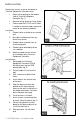
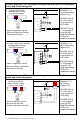
I NSTALLATION Remove the security screw on the bottom of Terminal Equipment Controller cover. Open unit by pulling on the bottom side of Terminal Equipment Controller (fig. 1). Remove wiring terminals from sticker. Please read the FCC ID and IC label installed in the cover upon removal of cover for the wireless products. Location 1. Should not be installed on an outside wall. 2. Must be installed away from any direct heat source. 3. Should not be installed near an air discharge grill. 4.
10. Insert each wire according to wiring diagram. 11. Gently push excess wiring back into hole (fig. 3). 12. Re-Install wiring terminals in their correct locations (fig. 3). 13. Re-install the cover (top side first) and gently push extra wire length back into the hole in the wall. 14. Install security screw. When replacing an existing Terminal Equipment Controller, label the wires before removal of the Terminal Equipment Controller. Electronic controls are static sensitive devices.
• • • • • • • • • • • • • • • • PIR and Stand-by setpoints supported. Local keypad lockable. PI time proportioning algorithm. Auxiliary output. Auto central system RTU changeover. Unique local configuration setup utility. C02 sensor input for monitoring and control. Configurable zone sequences of operation. Pre-engineered design, software and documentation. Self-discovering and self-binding database. Increased energy savings. Improves indoor air quality.
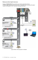
WIRELESS SYSTEM OVERVIEW Viconics VZ7260X5x00W Zone controllers are used in conjunction with the VZ7656X1000W Roof Top Controller controllers. Combined, they are designed for typical single or multistage RTU, HP’s and their associated local zones.
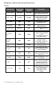
TERMINAL, IDENTIFICATION AND FUNCTION Wiring Terminal Identification VZ7260F Terminal Identification VZ7260C Description 4 - 24 V ~ Hot 24V ~Hot 24V ~Hot Power supply of controller, hot side (Delivered from the RTU). 5 - 0 V ~ Com 0V~Com 0V~Com Power supply of controller, common side. Also used as reference for the analog outputs when used. 6- On-Off Rht BO5 BO5 Local isolated triac reheat output when used. 7- On-Off Rht BO5 BO5 Local isolated triac reheat output when used.
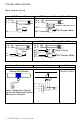
TYPICAL APPLICATIONS Main outputs wiring VAV Damper Wiring 24 V~ Hot 24 V~ Com 24 V~ Hot 24 V~ Com VAV Damper Motor Com 24 VAC 0-10 VDC AO 1 VAV Damper Wiring 24 V~ Hot 24 V~ Com VAV Damper Motor BO 1 BO 2 VAV Damper and Analog Reheat Wiring Com Open Close AO 2 AO 1 Com 24 VAC 0-10 VDC Reheat Valve or SCR Com 24 VAC 0-10 VDC VAV Damper Motor VAV Damper and Floating Reheat Wiring 24 V~ Hot 24 V~ Com BO 3 BO 4 BO 1 BO 2 Com Open Close Com Open Close Schematic Wiring Pressure dependent VAV cool
Mandatory RehtConf = 0 None Floating VAV Actuator Open Close UI3 0 V~ Com 24 V~ Hot Room Temperature Control Minimum & Maximum Position Adjusted at Controller BO1 BO2 Pressure dependent VAV cooling or heating system with central changeover Mandatory RehtConf = 0 None 0 to 10 Vdc Analog Actuator 0 to 10 VDC UI3 0 V~ Com 24 V~ Hot AO1 Room Temperature Control Minimum & Maximum Position Adjusted at Controller Mandatory RehtConf = 0 None Tri-State Floating Actuator Open Close UI3 0 V~ Com 24 V~ Hot B
Pressure dependent VAV cooling or heating system with local On-Off perimeter reheat and central changeover Mandatory RehtConf = 3 = On-Off Perimeter Reheat Only Analog VAV Actuator Heating and/or Cooling & On/Off Baseboard 0 to 10 VDC Set BO5 Time to 0= 15 minutes if using regular 24 VAC relays UI3 0 V~ Com 24 V~ Hot AO1 AO2 Set BO5 Time to 1= 10 seconds if using 24 VAC Solid State Relays (SSRs) for proportional control BO5-Aux R Room Temperature Control Minimum & Maximum Position Adjusted at Control
Tri-State Floating VAV Heating and/or Cooling & On/Off Duct Heater C 1 Mandatory RehtConf = 2 = On-Off Duct Reheat Only Open Close Set BO5 Time to 0= 15 minutes if using regular 24 VAC relays UI3 0 V~ Com 24 V~ Hot BO1 BO2 Set BO5 Time to 1= 10 seconds if using 24 VAC Solid State Relays (SSRs) for proportional control BO5-Aux BO5-Aux Room Temperature Control Min, Max and HeatFlow Positions Adjusted at Controller Pressure dependent VAV cooling or heating system with local Analog duct reheat and cent
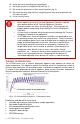
Remote sensor accessories Model no. S3010W1000 S2000D1000 Description Wall mounted temperature sensor Duct mounted temperature sensor Remote mount temperature sensors use 10K NTC thermistor. Temperature vs. Resistance Chart for 10 Kohm NTC Thermistor ºC ºF Kohm (R25°C = 10KΩ±3% - B25/85°C = 3975K±1.5%) ºC ºF Kohm ºC ºF Kohm ºC ºF Kohm ºC ºF Kohm -40 -40 324.3197 -20 -4 94.5149 0 32 32.1910 20 68 12.4601 40 104 5.3467 -39 -38 303.6427 -19 -2 89.2521 1 34 30.6120 21 70 11.
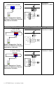
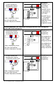
Wiring example of single remote room sensor: VZ7260 Series Controller S3010W1000 Remote wiring 1 sensor S2=On, S3=On Dip switch setting for: 1 sensor ON S2-1 = ON S2-2 = ON 1 2 Scom Scom RS RS Wiring examples of 2 remote room sensors for averaging applications: VZ7260 Series Controller 2 x S3010W1000 Remote wiring 2 sensors S2=On, S3=Off Scom RS Scom Scom RS RS Dip switch setting for: 2 sensors ON S2-1 = OFF S2-2 = ON 1 2 Wiring examples of 3 remote room sensors for averaging appli
CONFIGURING AND STATUS DISPLAY INSTRUCTIONS Status display The Terminal Equipment Controller features a two-line, eight-character display. There is a low backlight level that is always active and can only be seen at night. When left unattended, the Terminal Equipment Controller has an auto scrolling display that shows the current status of the system. Each item is scrolled sequentially with the back light in low level mode. Pressing any key will cause the back light to come on to high level.
USER INTERFACE User configuration menu • Unoccupied mode Override An Override can be made during an unoccupied period. If the Override option is enabled in the lockout configuration pressing the Override button will resume occupied setpoints for a time specified by the parameter; “ToccTime.” • Keypad interface Override Down Up An Override can be made during an Unoccupied period.
Local keypad interface An Override can be made during an unoccupied period.
Configuration Parameters Default Value PswrdSet Configuration parameters menu access password Default value = 0 No password prompted Zone MAC Zone Controller Controller network address Default Value: 255 PAN ID Personal Area Network Identification Default value = 0 Significance and Adjustments This parameter sets a password access to prevent unauthorized access to the configuration menu parameters. A default value of “0” will not prompt a password or lock the access to the configuration menu.
When PAN ID is used with a range of 251 to 500, for (SA) Stand-Alone Systems In this application, the VZ76 controller(s) are the coordinators to their own system. I.E. they are the network masters for each VZ72 controller reporting to them. • • • Wireless controller factory default Channel & PAN ID = Controller(s) offline VZ76 RTU controller is the network coordinator. Range of PAN ID on all controllers to use 251 to 500. This range is reserved for stand-alone system operation.
When PAN ID is used with a range of 1 to 250, for (NS) Networked Systems In this application, any controller(s) are simply router to the system. The VWG / JaceDriver is the coordinators to the system. I.E. the VWG / Jace-Driver is the network masters for ANY controller(s) reporting to them. • • • • Wireless controller factory default Channel & PAN ID = Controller(s) offline VWG Jace-Driver is the network coordinator Any controllers ( VZ72’s, VZ76xx RTU’s or any VT7xxx wireless controllers ) act as routers.
Channel Conditional parameter to Wireless models (VZ7260CX5x00W) only Channel selection This parameter will only appear when a wireless network adapter is present. If the thermostat is installed with a BACnet adapter, this parameter will not be used or displayed Default value = 10 This parameter (Channel) is used to link specific thermostats to specific Viconics wireless gateway(s) ( VWG / Jace-Driver) or main VZ76 RTU thermostat.
Get From Controller Get From another device configuration utility Default value = 255 Range is: 1 to 255 Entering a new MAC address enabled an automatic routine that automatically fetches all the required configuration property of the current device from another one already configured to the same required property values. If another value than the default value of 255 is entered, user will then be prompted to exit the Configuration Menu. Ex.
Lockout Keypad lockout levels Default value = 0 No lock 0 = No lock 1 = Low level 2 = Medium level 3 = High level USER KEY FUNCTIONS LEVEL Occupied temperature setpoints Local override only Global override access 0 1 2 3 BI1 Binary input no.1 configuration Default: None (None): No function will be associated with the input. Point can still be monitored through the BACnet™ network.
RehtConf Number of Reheat Stages and their applications 0 = None Default: 1 = Modulating Duct Reheat Only RTU in cooling mode uses Control Curve 1 RTU in heating mode uses Control Curve 2 1 = Modulating Duct Reheat Only Zone will operate in VAV heating or cooling only based on the Master RTU mode without any reheat.
5 = Duct heater & On-Off/Pulsed perimeter reheat (All electric) Zone will operate in VAV heating or cooling based on the Master RTU mode and use 2 stages of local reheat. The first reheat stage will use the modulating BO5 reheat output (10s or 15m cycles) for a local modulating electric duct reheat device with a 24 Vac fired SSR.
AO2RA/DA RA/DA Changes the action of the reheat 1 analog output. Valid only if analog reheat sequences are enabled DA = Direct acting Reverse acting or Direct acting 0 to 100 % = 0 to 10 VDC actuator signal for Reheat 1 RA = Reverse acting 0 to 100 % - 10 to 0 VDC Analog output signals Default: DA signal AO2 OALK VZ7260F5x00B models only Outdoor air temperature value from the RTU controller under which the analog reheat stage will be allowed to be used.
BO5 Time Valid only if reheat sequences are enabled with BO5 Sets the time base for the ON- 0= 15 minutes 1= 10 seconds for Solid state relays Off reheat output if used Default: 0 = 15 minute BO5 cont BO5 contact function Default value = 0 = NO Enables the use of normally opened or normally closed 2 position reheat valves.
St-By HT Stand-by heating setpoint Stand-by heating setpoint adjustment. This setpoint will be used if there is a motion detector connected and configured on BI1 or a PIR sensor cover used. Default: 65 °F (18°C) Heating setpoint range is: 40 to 90 °F (4.5 to 32.0 °C) St-By CL Stand-by cooling setpoint adjustment. This setpoint will be Stand-by cooling setpoint limit used if there is a motion detector connected and configured on BI1 or a PIR sensor cover used.
Pband Proportionnal band setting Default is : 3 Adjust the proportional band used by the controller PI control loop. Warning. Note that the default value of 3.0 °F (1.2 °C) gives satisfactory operation in most normal installation cases. The use of a superior proportional band different than the factory one is normally warranted in applications where the controller location is problematic and leads to unwanted cycling of the unit.
Min Pos Zone damper minimum position Sets the minimum position of the damper. 0 to 100% (Increments: 1% or 10%) Default : 10% Max Pos Zone damper maximum position Sets the maximum position of the damper for both heating and cooling mode of the RTU.
Not a configuration parameter. Only displays the controller’s performance in cooling mode. CL Perfo Controller’s cooling performance This value is only valid if there’s no change change in system mode, setpoints or occupancy for at least 1.5 hours.
REFERENCED O PERATIONAL CONTROL CURVES RehtConf = 0 = None VZ7260F Series: Analog Outputs Heating Setpoint CC1 Cooling Setpoint Device opened 10 Vdc or Max Pos DEAD BAND Device opened 10 Vdc or Max Pos AO1 AO1 Device closed Min Pos if DisMinPo = Enabled Heating Cooling Setpoint Setpoint DEAD BAND CC2 Device closed Min Pos if DisMinPo = Enabled or 0 Vdc if DisMinPo = Disabled or 0 Vdc if DisMinPo = Disabled Temperature increase Temperature increase RTC in Cooling mode RehtConf = 0 (No reheat
RehtConf = 1 = Analog Duct Reheat Only VZ7260F Series: Analog Outputs Device opened 100% Heating Setpoint DEAD BAND AO2 CC3 Cooling Setpoint Device opened 100% AO2 Device closed 0% Device opened 10 Vdc or Max Pos Heating Cooling Setpoint Setpoint DEAD BAND Device opened 10 Vdc or Max Pos Device opened MaxHeat Pos (1) Device closed 0% Device closed Min Pos if DisMinPo = Enabled AO1 AO1 Device closed Min Pos 0Vdc CC4 or 0 Vdc if DisMinPo = Disabled if DisMinPo = Disabled (2) Temperature
RehtConf = 2 = On-Off Duct Reheat Only VZ7260F Series: Analog Outputs Device opened 100% Cooling Setpoint DEAD BAND BO5 Device opened MaxHeat Pos (1) Device On CC5a Heating Setpoint Device opened 10 Vdc or Max Pos Cooling Setpoint DEAD BAND BO5 Output On Device opened 10 Vdc or Max Pos Device Off BO5 Output Off Device closed 0% AO1 AO1 Device opened MaxHeat Pos (1) Device closed Min Pos 0Vdc Device closed Min Pos Device closed Min Pos if DisMinPo = Enabled if DisMinPo = Disabled (2) Temp
VZ7260C Series: Floating Outputs Device opened 100% CC5a Heating Setpoint Cooling Setpoint DEAD BAND BO5 Device opened MaxHeat Pos (1) Device On BO5 Device opened 100% or Max Pos Heating Setpoint Cooling Setpoint DEAD BAND BO5 Output On CC5b Device opened 100% or Max Pos Device Off BO5 Output Off Device closed 0% BO1-BO2 BO1-BO2 Device opened MaxHeat Pos (1) Device closed Min Pos 0% Device closed Min Pos Device closed Min Pos if DisMinPo = Enabled if DisMinPo = Disabled (2) Temperature
RehtConf = 3 = On-Off Perimeter Reheat Only VZ7260F Series: Analog Outputs Device On BO5 Device Off Heating Cooling Setpoint Setpoint DEAD BAND CC6 Heating Setpoint Device On CC7 Cooling Setpoint DEAD BAND Device opened 10 Vdc or Max Pos BO5 Device opened 10 Vdc or Max Pos Device Off Device closed Min Pos if DisMinPo = Enabled AO1 or 0 Vdc if DisMinPo = Disabled AO1 AO1 Device closed Min Pos AO1 = 0Vdc if DisMinPo = Disabled Temperature increase Temperature increase RTC in Heating mode
RehtConf = 4 = Analog Duct Reheat & On-Off Perimeter Reheat VZ7260F Series: Analog Outputs Heating Setpoint Device On BO5 Cooling Setpoint DEAD BAND CC9 Device On Device Off AO2 Device opened Max Heat Pos (1) Device Opened 100% AO2 Device Closed 0% Device opened 10 Vdc or Max Pos Device closed 0% AO1 Device closed Min Pos CC10 BO5 Device Off Device opened 10 Vdc or Max Pos Device opened 100% Heating Cooling Setpoint Setpoint DEAD BAND Device closed Min Pos if DisMinPo = Enabled AO1 or
RehtConf = 5 = Pulsed Duct heater & On-Off/Pulsed perimeter reheat (All electric) VZ7260C Series: Floating Outputs Heating Setpoint Device On Cooling Setpoint DEAD BAND BO3 CC11a Heating Setpoint Device On Device Off BO4 Cooling Setpoint DEAD BAND CC11b BO3 Device 100% Device opened 100% or Max Pos BO5 Device 0% Device opened Max Heat Pos (1) Device closed Min Pos Device Off BO4 Device opened 100% or Max Pos BO5 Output On BO1-BO2 0% Device opened MaxHeat Pos (1) BO5 Output Off D
S PECIFICATIONS Terminal Equipment Controller power requirements: Operating conditions: Storage conditions: Sensor: Resolution: Temperature control accuracy: Contact output rating: Occ, Stand-By and Unocc cooling setpoint range: Occ, Stand-By and Unocc heating setpoint range: Room and outdoor air temperature display range: Proportional band for room temperature control: Binary inputs: AI4 Analog input: Wire gauge: Approximate shipping weight: Agency Approvals all models: Agency Approvals all models: Agen
DRAWING & DIMENSIONS Viconics Technologies Inc. 9245 Langelier Blvd. I St-Leonard I Quebec I Canada I H1P 3K9 Tel.: (514) 321.5660 I Fax: (514) 321.4150 Toll free: 1 800.563.5660 sales@viconics.com I www.viconics.