VZ7656E1000W Zigbee™ Wireless RTU Terminal Equipment Controller with IAQ Control Installation Guide F o r C o m m e r c i a l Z o n i n g S ys t e m s th January 10 , 2012 / 028-0327-R1 CONTENTS Installation Location Installation Theory of Operation Features overview Wireless System Overview Terminal, Identification and Function Wiring Screw terminal arrangement and wiring Typical Applications Main outputs wiring Remote sensor accessories Configuring and Status Display Instructions Status display User in
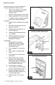
I NSTALLATION Remove the security screw on the bottom of Terminal Equipment Controller cover. Open unit by pulling on the bottom side of Terminal Equipment Controller (fig. 1). Remove wiring terminals from sticker. Please read the FCC ID and IC label installed in the cover upon removal of cover for the wireless products. Location 1. Should not be installed on an outside wall. 2. Must be installed away from any direct heat source. 3. Should not be installed near an air discharge grill. 4.
10. Insert each wire according to wiring diagram. 11. Gently push excess wiring back into hole (fig. 3). 12. Re-Install wiring terminals in their correct locations (fig. 3). 13. Re-install the cover (top side first) and gently push extra wire length back into the hole in the wall. 14. Install security screw. When replacing an existing Terminal Equipment Controller, label the wires before removal of the Terminal Equipment Controller. Electronic controls are static sensitive devices.
Remote outdoor sensing capability for added flexibility. System mode heating and cooling lockout. Zone perimeter reheat lockout. Remote discharge air sensor input for monitoring and control purpose. System efficiency feedback. Discharge high limit heating lockout. Discharge low limit cooling lockout. Remote return air sensor input for monitoring control. System efficiency feedback. Return high limit heating lockout. Return low limit cooling lockout. Communication lost control function.
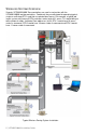
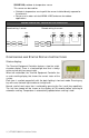
WIRELESS SYSTEM OVERVIEW Viconics VZ7260X5X00W Zone controllers are used in conjunction with the VZ7656X1000W roof top controllers. Combined, they are designed for operating typical; single or multistage RTU’s and their associated local zones. For example, a typical job layout system may feature 3 RTU controllers and a total of 31 zones. This would bring to total number of nodes (individual Com addresses) to 34.
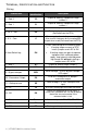
TERMINAL , IDENTIFICATION AND FUNCTION Wiring Terminal Identification Description 1 – Cool 2 Y2 Output for cooling / compressor stage number 2. 2 – Cool 1 Y1 Output for cooling / compressor stage number 1. 3 - Fan G Output for the fan. 4 - 24 V ~ Hot RC Power supply of controller, hot side (Delivered from the RTU). 5 - 0 V ~ Com C Power supply of controller, common side. Also used as reference for the analog BPD output when used (Delivered from the RTU).
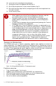
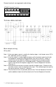
Screw terminal arrangement and wiring VZ7656E Controller Terminals Y2 Y1 BPD EC G RC SP AI C RH W1 W2 RS SCom OS DS TYPICAL APPLICATIONS Main outputs wiring Wiring notes: Note 1: If the same power source is used for the heating stages, install jumper across RC & RH. Maximum current is 2.0 amps. Note 2: If auxiliary output is used to toggle occupancy of the electronic control card inside the equipment, configure the relay parameter (Aux cont) to the N.O. setting.
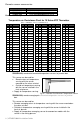
Remote sensor accessories Model no. Description S2020E1000 Outdoor temperature sensor S2060A1000 Averaging temperature sensor S2000D1000 Duct mounted temperature sensor Remote mount temperature sensors use 10K NTC thermistor. Temperature vs. Resistance Chart for 10 Kohm NTC Thermistor ºC ºF Kohm (R25°C = 10K±3% - B25/85°C = 3975K±1.5%) ºC ºF Kohm ºC ºF Kohm ºC ºF Kohm ºC ºF Kohm -40 -40 324.3197 -20 -4 94.5149 0 32 32.1910 20 68 12.4601 40 104 5.3467 -39 -38 303.6427 -19 -2 89.
S2020E1000; outdoor air temperature sensor This sensor can be used for: Outside air temperature sensing with the sensor installed directly exposed to the elements. Sensor uses a water resistant NEMA 4 ABS enclosure for outdoor applications.
Sequence of auto-scroll status display: CLOCK STATUS SYSTEM MODE SCHEDULE STATUS OUTDOOR TEMPERATURE Monday 12:00 AM Sys mode auto Occupied Outdoor x.x °C or°F Sys mode off Sys mode heat Sys mode cool Occupied hold Unoccup ALARMS DAS Alarm FA Alarm SetClock High CO2 Com Lost Outdoor air temperature Outdoor air temperature display is only enabled when outdoor air temperature sensor is connected. A maximum range status display of 50 °C (122 °F) indicates a shorted sensor.
Current Zone Sequence Zone Seq Off Zone Seq Cool Zone Seq Heat Return Air Temperature Discharge Air Temperature RA Temp xx.x °C or °F DA Temp xx.x °C or °F Effective PI Heat Effective PI Cool Demand at RTU Demand at RTU Effective CO2 Level at RTU Current Static Pressure Pressure x.
It is possible to bring up the user menu at any time by depressing the MENU key. The status display automatically resumes after exiting the user-configuring menu. If the user pauses at any given time during configuring, Auto Help text is displayed to help and guide the user through the usage and configuring of the controller. Ex.
A) Override an unoccupied period Override schd Y/N This menu will appear only when the controller is in unoccupied mode. The unoccupied mode is enabled either by the internal timer scheduling or by a network unoccupied command on the occupancy object. If DI1 is configured to operate as a remote temporary override contact, this menu will be disabled.
D) Schedule set (2 events) Scheduling can have 2 or 4 events per day. This is set in the configuration menu as per parameter; (2/4event). Schedule set Y/N This section of the menu permits the user to set the weekly schedule for all the zones attached to the RTU controller. Each day can be tailored to specific schedules if needed. 2 events can be configured per day. Occupied & unoccupied periods can be set for each day.
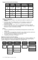
Ex. #2 Commercial building which is occupied all weekend Event Period #1 - Event Period #1 - Event #1 #2 Occupancy Occupied Unoccupied Daily Occupancy Monday 8.00 AM 5.00 PM Day time only Tuesday 8.00 AM 5.00 PM Day time only Wednesday 8.00 AM 5.00 PM Day time only Thursday 8.00 AM 5.00 PM Day time only Friday 8.00 AM 5.00 PM Day time only Saturday 12.00 AM ** 11.59 PM ** Occupied Sunday 12.00 AM ** 11.
Ex. #1. Four event retail establishment schedule Monday Tuesday Wednesday Period 1 Event 1 Occupied Cool Heat 72°F 70°F 7.00 AM 7.00 AM 7.00 AM Period 1 Event 2 Unoccupied Cool Heat 80°F 62°F 5.00 PM 5.00 PM 5.00 PM Period 2 Event 3 Occupied Cool Heat 72°F 70 °F 12.00 PM * 12.00 PM * 12.00 PM * Period 2 Event 4 Unoccupied Cool Heat 80°F 62 °F 12.00 PM * 12.00 PM * 12.00 PM * Thursday 7.00 AM 5.00 PM 7.00 PM 10.30 PM Friday 7.00 AM 5.00 PM 7.00 PM 10.30 PM Saturday Sunday 12.00 PM * 12.
CONFIGURATION PARAMETERS DEFAULT VALUE PswrdSet Configuration parameters menu access password Default value = 0 No password prompted RTC MAC Zone Controller Controller network address Default Value: 4 PAN ID Personal Area Network Identification Default value = 0 Range is: 0 to 500 SIGNIFICANCE AND ADJUSTMENTS This parameter sets a password access to prevent unauthorized access to the configuration menu parameters.
When PAN ID is used with a range of 251 to 500, for (SA) Stand-Alone Systems In this application, the VZ76 controller(s) are the coordinators to their own system. I.E. they are the network masters for each VZ72 controller reporting to them. Wireless controller factory default Channel & PAN ID = Controller(s) offline VZ76 RTU controller is the network coordinator. Range of PAN ID on all controllers to use 251 to 500. This range is reserved for stand-alone system operation.
When PAN ID is used with a range of 1 to 250, for (NS) Networked Systems In this application, any controller(s) are simply router to the system. The VWG / JaceDriver is the coordinators to the system. I.E. the VWG / Jace-Driver is the network masters for ANY controller(s) reporting to them. Wireless controller factory default Channel & PAN ID = Controller(s) offline VWG Jace-Driver is the network coordinator Any controllers ( VZ72’s, VZ76xx RTU’s or any VT7xxx wireless controllers ) act as routers.
Channel This parameter (Channel) is used to link specific controllers to specific Viconics wireless gateway(s) (VWG / Jace-Driver) or to the main VZ76xx RTU controller. For any system, be sure you set the SAME channel value both at the network coordinator and on all the VZ72xx controller(s). Channel selection Default value = 10 Range is: 10 to 26 Viconics recommends using only the following channels: 15, 25 & 26. The default value of 10 is NOT a valid channel.
CntrlTyp Sets how the Zones attached to the RTU controller vote to determine the actual system mode of operation. (Heat or Cool) Default Value: 1 = AV_H3 This parameter will select the type of operation required for the RTU based on the size of the system. Please refer to the Viconics Zoning System Guide for recommended settings. Only the Zones that actually have values above 0% in their (PIHT Wei & PICL Wei) configuration parameters will be able to vote on the RTU operational mode calculation.
Cool cph Will set the maximum number of cooling stage cycles per Cooling stages cycles per hour under normal control operation. It represents the hour maximum number of cycles that the equipment will be turned on and off in the span of an hour. Default value = 4 C.P.H. Note that a higher C.P.H will represent a higher accuracy of control at the expense of wearing down mechanical components faster. 3 or 4 C.P.H.
Cal OS Outside air temperature sensor calibration Default value = 0.0 °F or °C Offset that can be added/subtracted to actual displayed outside air temperature ± 5.0 °F ( ± 2.5 °C ) H stage Will revert the operation of 2 stage controllers to a single Number of heating stages stage when the second heating step is not needed. installed at RTU.
Prog rec Off, = no progressive recovery. Progressive recovery enabled The programmed occupied schedule time is the time at which the system will restart and send the occupied status Default value = Off to the attached zones. On, = progressive recovery active.
Pressure Static Pressure setpoint Default: 0.8”WC Bypass damper will maintain this supply static pressure set point. Please refer to the Viconics Zoning System Guide for recommended settings. 0 to 2 in WC (0 Pa to 500 Pa) (increments: 0.1” WC or 25 Pa) SP Cntrl Depending on the setting of this parameter, the 0-10VDC pressure control output (labled BPD) will either have a Static Pressure Control Type 0VDC or 10VDC output when the fan is Off.
Min FA Minimum Fresh Air Value Default value = 0 CFM Minimum fresh air required. Effective only in Occupied mode (Fan is ON). This value is used to determine the fresh air damper position based on the Min/Max CO2 and Min/Max FA values (if FA Range is set to other than 0 CFM). See Fresh Air Damper Position section for more details.
FRESH AIR DAMPER CONTROL SEQUENCES The fresh air damper can be controlled through more than one sequence to achieve different control strategies such as free cooling (economizer mode), minimum fresh air control and CO2 level control. Here are the control sequences available: Note: For the sequences mentioned below, the following conditions must be met in order for the sequences to be performed as stated: - Max Pos parameter value must be greater than Min Pos Parameter value.
Economizer Mode and Fresh Air Measurement Station If the fresh air damper is to be used for both free cooling and minimum fresh air volume control (economizer mode and fresh air measurement station, but without CO 2 level control), only the Min FA parameter and the free cooling sequence will be active. - The FA Range parameter should be set to a value higher than 0 CFM (0 CFM disables the fresh air control). Min FA (minimum fresh air) parameter should be set to the desired level.
Economizer Mode and CO 2 Level Control If the fresh air damper is to be used for both free cooling and CO 2level control (economizer mode and CO2 level control, but without fresh air measurement station), only the Min Pos, Max Pos, Min CO2and Max CO2 parameters as well as the free cooling sequence will be active. - The FA Range parameter should be set to 0 CFM.
Economizer Mode, CO 2 Level Control and Fresh Air Measurement Station If the fresh air damper is to be used for both free cooling and CO 2 level control with a fresh air measurement station, only the Min FA, Max FA, Min CO2 and Max CO2 parameters as well as the free cooling sequence will be active. - The FA Range parameter should be set to something other than 0 CFM.
S PECIFICATIONS Terminal Equipment Controller power requirements: Operating conditions: Storage conditions: Sensor: Resolution: Temperature control accuracy: Contact output rating Occ, Stand-By and Unocc cooling setpoint range: Occ, Stand-By and Unocc heating setpoint range: Room and outdoor air temperature display range: Supply air temperature range: Static pressure and air flow analog inputs Digital inputs: By-Pass damper and economizer analog outputs rating By-Pass damper and economizer analog outputs ac
DRAWING & DIMENSIONS Viconics Technologies Inc. Tel.: 32 | VZ7656E1000W Installation Guide Fax: Toll free: www.viconics.