VZ7656R1000W / VZ7656H1000W Zigbee™ Wireless RTU / HP Terminal Equipment Controllers Installation Guide F o r C o m m e r c i a l Z o n i n g S ys t e m s th January 10 .
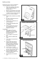
I NSTALLATION Remove the security screw on the bottom of Terminal Equipment Controller cover. Open unit by pulling on the bottom side of Terminal Equipment Controller (fig. 1). Remove wiring terminals from sticker. Please read the FCC ID and IC label installed in the cover upon removal of cover for the wireless products. Location 1. Should not be installed on an outside wall. 2. Must be installed away from any direct heat source. 3. Should not be installed near an air discharge grill. 4.
10. Insert each wire according to wiring diagram. 11. Gently push excess wiring back into hole (fig. 3). 12. Re-Install wiring terminals in their correct locations (fig. 3). 13. Re-install the cover (top side first) and gently push extra wire length back into the hole in the wall. 14. Install security screw. When replacing an existing Terminal Equipment Controller, label the wires before removal of the Terminal Equipment Controller. Electronic controls are static sensitive devices.
Remote discharge air sensor input for monitoring and control purpose. System efficiency feedback. Discharge high limit heating lockout. Discharge low limit cooling lockout. Remote return air sensor input for monitoring control. System efficiency feedback. Return high limit heating lockout. Return low limit cooling lockout. Communication lost control function. Password protected configuration menu and lockable keypads for security. A configurable digital input for added flexibility.
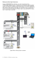
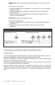
WIRELESS SYSTEM OVERVIEW Viconics VZ72605x00W Zone Controllers are used in conjunction with the VZ7656x1000W roof top controllers. Combined, they are designed for operating typical; single or multistage RTU’s and their associated local zones. For example, a typical job layout system may feature 3 RTU controllers and a total of 31 zones. This would bring to total number of nodes (individual Com addresses) to 34.
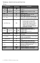
TERMINAL , IDENTIFICATION AND FUNCTION Wiring Terminal Use Rooftop 1 – Cool 2 2 – Cool 1 Heat pump Compressor 2 Compressor 1 Terminal Identification RTU HP Y1 G 4 - 24 V ~ Hot RC 5 - 0 V ~ Com C 6 – Heat Switch Leg RH 7 – Heat 1 W1 8 –Heat 2 Reversing valve 9 – By-pass damper W2 O/B BPD 10 – Aux output AU 11 – Static pressure SP 12 - DI1 DI 13 - RS RS 14 - Scom 15 - OS 16 - DS Output for cooling / compressor stage number 2. Output for cooling / compressor stage number 1.
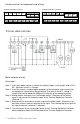
Screw terminal arrangement and wiring VZ7656H Controller Terminals VZ7656R Controller Terminals Y2 BPD Y1 Aux G SP RC DI1 Y2 C RS RH W1 W2 SCom OS DS BPD Y1 Aux G SP RC DI1 C RS RH W1 O/B SCom OS DS TYPICAL APPLICATIONS Main outputs wiring Wiring notes: Note 1: If the same power source is used for the heating stages, install jumper across RC & RH. Maximum current is 2.0 amps.
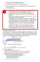
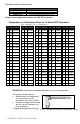
Remote sensor accessories Model no. S2020E1000 S2060A1000 S2000D1000 Description Outdoor temperature sensor Averaging temperature sensor Duct mounted temperature sensor Remote mount temperature sensors use 10K NTC thermistor. Temperature vs. Resistance Chart for 10 Kohm NTC Thermistor (R25°C = 10K±3% - B25/85°C = 3975K±1.5%) ºC ºF Kohm ºC ºF -40 -40 324.3197 -20 -39 -38 303.6427 -38 -36 284.4189 Kohm ºC ºF -4 94.5149 0 -19 -2 89.2521 -18 0 84.3147 -37 -35 266.5373 -17 1 -36 -33 249.
S2060A1000; remote averaging duct mounted temperature sensor c/w junction box. This sensor can be used for: Remote averaging return air temperature sensing with the sensor mounted on the return air duct. Outside air temperature averaging sensing with the sensor installed in the fresh air plenum. Supply air temperature averaging sensor for economizer models with the sensor in the mixing plenum.
Sequence of auto-scroll status display: CLOCK STATUS SYSTEM MODE SCHEDULE STATUS OUTDOOR TEMPERATURE Monday 12:00 AM Sys mode auto Occupied Outdoor x.x °C or°F Sys mode off Sys mode heat Sys mode cool Occupied hold Unoccup ALARMS Service DAS Alrm SetClock Filter Comm Lost Outdoor air temperature Outdoor air temperature display is only enabled when outdoor air temperature sensor is connected. A maximum range status display of 50 °C (122 °F) indicates a shorted sensor.
Current Zone Sequence Return Air Temperature Zone Seq Off Zone Seq Cool Zone Seq Heat Effective PI Heat Demand at RTU Heat Out xxx % RA Temp xx.x °C or °F Effective PI Cool Demand at RTU Cool Out xxx % Discharge Air Temperature DA Temp xx.x °C or °F Highest PI Heat Demand Zone Address Heat MAC xxx Current Static Pressure Pressure x.
Ex.: Press yes key to change cooling temperature setpoint Use the up or down arrow to adjust cooling setpoint Each of the sections in the menu is accessed and configured using 5 keys on the controller cover. The priority for the alarms is as follows: Local keypad interface The YES key is used to confirm a selection, to move onto the next menu item and to manually scroll through the displayed information. The NO key is used when you do not desire a parameter change, and to advance to the next menu item.
Override schd Y/N This menu will appear only when the controller is in unoccupied mode. The unoccupied mode is enabled either by the internal timer scheduling or by a network unoccupied command on the occupancy object. If DI1 is configured to operate as a remote temporary override contact, this menu will be disabled. Answering yes to this prompt will cause the all the zones attached to the RTU controller to go into occupied mode for an amount of time equal to the parameter “TOccTime” (1 to 12 hours).
2 events can be configured per day. Occupied & unoccupied periods can be set for each day.
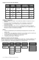
Ex. #2 Commercial building which is occupied all weekend Event Period #1 - Event Period #1 - Event #1 #2 Occupancy Occupied Unoccupied Daily Occupancy Monday 8.00 AM 5.00 PM Day time only Tuesday 8.00 AM 5.00 PM Day time only Wednesday 8.00 AM 5.00 PM Day time only Thursday 8.00 AM 5.00 PM Day time only Friday 8.00 AM 5.00 PM Day time only Saturday 12.00 AM ** 11.59 PM ** Occupied Sunday 12.00 AM ** 11.
Ex. #1. Four event retail establishment schedule Monday Tuesday Wednesday Period 1 Event 1 Occupied Cool Heat 72°F 70°F 7.00 AM 7.00 AM 7.00 AM Period 1 Event 2 Unoccupied Cool Heat 80°F 62°F 5.00 PM 5.00 PM 5.00 PM Period 2 Event 3 Occupied Cool Heat 72°F 70 °F 12.00 PM * 12.00 PM * 12.00 PM * Period 2 Event 4 Unoccupied Cool Heat 80°F 62 °F 12.00 PM * 12.00 PM * 12.00 PM * Thursday 7.00 AM 5.00 PM 7.00 PM 10.30 PM Friday 7.00 AM 5.00 PM 7.00 PM 10.30 PM Saturday Sunday 12.00 PM * 12.
I NSTALLER CONFIGURATION P ARAMETER MENU Configuration can be done through the network or locally at the Terminal Equipment Controller. To enter configuration, press and hold the middle button “Menu” for 8 seconds If a password lockout is active, “Password” is prompted. Enter password value using the “up” and “down” arrows and press “Yes” to gain access to all configuration properties of the Terminal Equipment Controller.
When PAN ID is used with a range of 251 to 500, for (SA) Stand-Alone Systems In this application, the VZ76 controller(s) are the coordinators to their own system. I.E. they are the network masters for each VZ72 controller reporting to them. Wireless controller factory default Channel & PAN ID = controller(s) offline VZ76 RTU controller is the network coordinator. Range of PAN ID on all controllers to use 251 to 500. This range is reserved for stand-alone system operation.
When PAN ID is used with a range of 1 to 250, for (NS) Networked Systems In this application, any controller(s) are simply router to the system. The VWG / JaceDriver is the coordinators to the system. I.E. the VWG / Jace-Driver is the network masters for ANY controller(s) reporting to them. Wireless controller factory default Channel & PAN ID = controller(s) offline VWG Jace-Driver is the network coordinator Any controllers ( VZ72’s, VZ76xx RTU’s or any VT7xxx wireless controllers ) act as routers.
lockout Keypad lockout levels 0 = No lock 1 = Low level Default value = 0 No lock 2 = High level USER KEY FUNCTIONS LEVEL Global Unocc. Override 0 1 2 pwr del Power-up delay Default value = 10 seconds CntrlTyp Sets how the Zones attached to the RTU controller vote to determine the actual system mode of operation.
Dis LL Discharge air temperature low limit Default: 45°F Anticycl Discharge air low temperature value at which the cooling stages will be locked out. 35 to 65°F (2.0°C to 19.0°C) (increments: 0.5° or 5°) Minimum On/Off operation time of cooling & heating Minimum on/off operation time stages. for stages Default value = 2 minutes. IMPORTANT, anti-short cycling can be set to 0 minutes for equipment that possess their own anti cycling timer.
fan del Fan delay Default value = Off DI 1 Digital input 1 configuration Default value = None Fan delay extends fan operation by 60 seconds after the call for heating or cooling ends. Valid only for Auto fan mode. “On” fan mode will leave the fan always on. Off or On Open contact input = function not energized. Closed contact input = function energized. None: No function will be associated with the input. Rem NSB, remote NSB timer clock input. Will disable the internal scheduling of the controller.
EH Mode Enables or disables the Emergency Heat mode from VZ7656H1000B models only displaying in the System mode.
C lock Outside air temperature mechanical cooling lockout. Default value = -40 °F ( 40 °C ) Disables cooling stage operation based on outdoor air temperature. On economizer model, free cooling will not be disabled by this function. Function will only be enabled if OS (outside air temperature sensor) is connected.
Prog rec Off, = no progressive recovery. Progressive recovery enabled The configured occupied schedule time is the time at which the system will restart and send the occupied status to the attached zones. Default value = Off On, = progressive recovery active. Progressive recovery is automatically disabled if BI 1 is configured remote NSB The configured occupied schedule time is the time at which the desired occupied temperature setpoints will be attained at the Zones.
Pressure Static Pressure setpoint Default: 0.8”WC Bypass damper will maintain this supply static pressure set point. Please refer to the Viconics Zoning System Guide for recommended settings. 0 to 2 in WC (0 Pa to 500 Pa) (increments: 0.1” WC or 25 Pa) SP Cntrl Depending on the setting of this parameter, the 0-10VDC Static Pressure Control Type pressure control output (labled BPD) will either have a 0VDC or Default: BPD BPD (By-Pass Damper): 10VDC when fan is Off 10VDC output when the fan is Off.
Comp/aux Sets the operation and interaction mode of the heat pump with Compressor/auxiliary the auxiliary heat. interlock Interlock Off. In Heating mode. Default value = Off If the heat pump is not able to satisfy the heating setpoint, the auxiliary heat will be energized at the same time as the heat pump stage. Typically applies when the air handler heat pump coil is installed before the auxiliary heat. ( all electric systems ) Interlock On. In Heating mode.
S PECIFICATIONS Terminal Equipment Controller power requirements: Operating conditions: Storage conditions: Sensor: Resolution: Temperature control accuracy: Contact output rating Occ, Stand-By and Unocc cooling setpoint range: Occ, Stand-By and Unocc heating setpoint range: Room and outdoor air temperature display range: Digital inputs: By-pass damper/VFD analog output rating By-pass damper /VFD analog output accuracy: Wire gauge: Approximate shipping weight: Agency Approvals all models: Agency Approvals
DRAWING & DIMENSIONS Viconics Technologies Inc. Tel.: Fax: 29 | VZ7656R & VZ7656H-Installation Guide Toll free: www.viconics.