Javelin III Power Supply Operator’s Manual III Power Supply Power Factor Corrected AC-DC Switcher Operator’s Manual and “Quick Install” Instructions www.mpwrs.com Rev. 05/11/2012 Mission Power Solutions (760) 631-6846 sales@mpwrs.com Pg.
Javelin III Power Supply Operator’s Manual Javelin III Power Supply AC-DC Switcher Javelin III Power Supply “Quick Install” Instructions Mounting the Javelin III Power Supply The Javelin III can be mounted at either of two surfaces (top or bottom). Use #8-32 mounting screws. Maximum penetration should not exceed 0.21″ (5.33mm). Maintain 2” (50,8mm) clearance at either end for airflow. Input Connections Input Barrier Strip (TB1) Input AC or DC power is applied to barrier strip TB1.
Javelin III Power Supply Operator’s Manual Status/Control/Sense Connector (J1) 15 J1-1 and J1-9 are Signal Return pins. J1-2 is VCC +5V @ 300mA. J1-3 is AC Power OK (+5V = True). J1-4, 5 and 12 are not connected J1-5 is +12V fan power. J1-6 is +5V DC (in). J1-7 is DC OK and J1-8 is DC OK′. J1-10 and J1-11 are used in conjunction according to Table 2. J1-13 is +Remote Sense and J1-14 is –Remote Sense.
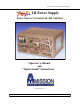
Javelin III Power Supply Operator’s Manual III Power Supply Power Factor Corrected AC-DC Switcher Overview The Javelin III is a ruggedized, switching power supply that combines the advantages of power factor correction and power density with user-selectable output voltage and power. Accepting input voltages of 85 to 254 VAC and 85 to 380 VDC, the Javelin III can provide up to 5400 watts in a 7.00”H x 16.0”W x 13.0”L package.
Javelin III Power Supply Operator’s Manual Technical Description The Javelin III consists of an off-line single phase or three phase power-factor-corrected front end (or optional DC), with EMI filter, cooling fans, customer interface, associated housekeeping circuits, and a selection of Vicor’s DC-DC converters. Three power supply units are placed in parallel to provide the final output current capability.
Javelin III Power Supply Operator’s Manual Input Line Filter Rectifier Soft Start Circuit Boost Converter Output Power Output Waveform Sample Current Sample PFC Control Inhibit/Enable Control Inhibit/Enable Customer Interface I/E Control Housekeeping Power Fan Figure 1. Javelin III Architecture Interface Connections Input Power Terminal (TB1) Input AC (and DC) Power is applied to connector TB1 using a #8 ring lugs. See Table 1 (Pg. 2) for input connector assembly instructions.
Javelin III Power Supply Operator’s Manual Signal Return (J1-1, 9) Signal Return on J1-1 & 9 is an isolated secondary ground reference for all J1 interfacing signals. Inhibit/Enable (J1-10 & J1-11) The Inhibit/Enable control pins allow the output to be controlled with either “inhibit” or “enable” logic. Connecting Inhibit (J1-11) and Enable (J1-10) to ground causes the Javelin III to operate. With Inhibit (J1-11) open, the Javelin III will operate, and the Enable pin has no effect.
Javelin III Power Supply Operator’s Manual DC OK/DC OK′ (J1-7 and J1-8) DC OK and DC OK′ are logic signals provided to indicate with either TTL logic “1” or “0” that the correct output voltage is available. DC OK (J1-7) is a logic “1” when output voltage is within specification and a logic “0” when output is out of tolerance. A logic “0” is capable of sinking 16 mA in either circuit. The inverse signal, DC OK′, is available at J1-8.
Javelin III Power Supply Operator’s Manual Mechanical Drawing - Javelin III Rev. 05/11/2012 Mission Power Solutions (760) 631-6846 sales@mpwrs.com Pg.
Javelin III Power Supply Operator’s Manual Specifications (Typical at 25C, nominal line and 75% load, unless otherwise specified) General Number of Outputs Efficiency Safety Approvals MIL-STD’s Maximum Output Power 1 75% N/A 461E; 704E; 810E; 1399 2400W, 115 VAC 3600W, 230 VAC 5400W, 230 VAC (Selected Output Voltages) Input Input 85-254 VAC, 47-500Hz 100-380 VDC 0.2% from 10% load to full load 90A rms. max. @ 115 VAC 180A rms. max. @ 230 VAC 60A rms.
Javelin III Power Supply Operator’s Manual Environmental 810E MIL-STD Storage Temperature 40C to 125C 40C to 125C 55C to 125C 65C to +125C C Grade T Grade H Grade M Grade Operating Temperature 20C to 55C 20C to 70C 40C to 55C 40C to 70C 40C to 55C 40C to 70C 55C to +55C 55C to +70C C Grade, Full Power C Grade, Half Power T Grade, Full Power T Grade, Half Power H Grade, Full Power H Grade, Half Power M Grade, Full Power M Grade, Half Power Product Weight Dim
Javelin III Power Supply Operator’s Manual Javelin III Maximum Output Power vs. Temperature 6000 1200W 5000 1800W 2400W Pout max 4000 3600W 4800W 5400W 3000 2000 1000 0 0 20 40 60 80 100 Temperature, Ambient (C) Graph 2. Maximum Output Power Vs. Temperature Rev. 05/11/2012 Mission Power Solutions (760) 631-6846 sales@mpwrs.com Pg.
Javelin III Power Supply Operator’s Manual Notes Rev. 05/11/2012 Mission Power Solutions (760) 631-6846 sales@mpwrs.com Pg.