
Manual
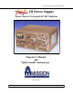


Javelin III Power Supply Operator’s Manual
Javelin III Power Supply
AC-DC Switcher
Javelin III Power Supply “Quick Install” Instructions
The Javelin III can be mounted at either of two surfaces (top or bottom).
Use #8-32 mounting screws. Maximum penetration should not exceed
0.21″ (5.33mm).
Maintain 2” (50,8mm) clearance at either end for airflow.
Input Connections
Input Barrier Strip (TB1)
Mounting the Javelin III Power Supply
Rev. 05/11/2012 Mission Power Solutions (760) 631-6846 sales@mpwrs.com Pg. 2
Input AC or DC power is applied to barrier strip TB1. See Table 1 for
single phase, DC, 3 phase/3 wire, or 3 phase/4 wire.
To connect, use #8 ring lugs with 30A rating.
Grounding stud provided for ground connection(s) to the right of TB1.
A fault-clearing device, such as a fuse or circuit breaker, with a maxi-
mum rating per Table 1 at the power supply input is required for
safety agency compliance.
1
Single Phase
2
DC
3
3 Phase/3 Wire
4
3 Phase/4 Wire
TB1-1 L1 TB1-1 + TB1-1 A TB1-1 A
TB1-2 L2/N TB1-2 – TB1-2 B TB1-2 B
TB1-3 C TB1-3 C
TB1-4 N
Current Requirements
30A AC 30A DC 17A AC per phase 10A AC per phase
Maximum Fuse Rating
45A 45A 25A per phase 15A per phase
Table 1. AC and DC Input Connections