
User guide

Before initial power-up follow these steps to configure the
evaluation board for specific end application requirements:
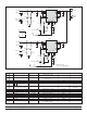
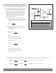
2.0 Undervoltage (UV) and Overvoltage (OV) resistors set up:
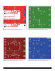
2.1 UV and OV programmable resistors are configured
for a 3.3 V Vin (BUS voltage) application in a two-
resistor voltage divider configuration as shown in
Figure 4. UV is set to 2.6 V and OV is set for 3.8 V,
R1
OV
and R1
UV
are 2.00 KΩ 1%. If PI2121-EVAL1 is
required to be used in a different Vin voltage
application please follow the following steps to
change the resistor values.
2.1.1 It is important to consider the maximum
current that will flow in the resistor divider
and maximum error due to UV and OV input
current.
R1
UV
=
V(UV
TH
)
I
RUV
2.1.2 Set R1
UV
and R1
OV
value based on system
allowable minimum current and 1% error;
I
RUV
≥ 100 µA
R2
UV
=R1
UV
(
V(UV)
–1
)
V(UV
TH
)
Where:
V(UV
TH
) : UV threshold voltage
V(UV) : UV voltage set (0.5 V typ)
I
RUV
: R1
UV
current
R2
OV
=R1
OV
(
V(OV)
–1
)
V(OV
TH
)
Where:
V(OV
TH
) : OV threshold voltage
V(OV) : OV voltage set (0.5 V typ)
I
ROV
: R1
OV
current
PI2121
UV
OV
FT
FT
V_Logic
GND
R2
UV
R1UV
R2
OV
R1OV
Vin
Figure 4 – UV & OV two-resistor divider configuration
Ref. Desg. SiP1 SiP2
R1
UV
R3 R10
R2
UV
R1 R8
R1
OV
R4 R11
R2
OV
R2 R9
Picor Corporation • www.picorpower.com PI2121-EVAL1 User Guide Rev 1.1 Page 5 of 12
2.1.3 Example for 2.0 V Vin (BUS voltage), to set UV and OV for ±10% Vin set UV at 1.8 V and OV at 2.2 V.
R2
UV
= R1
UV
(
V(UV)
–1
)
= 2.00 KΩ
*
(
1.8 V
–1
)
= 5.20 KΩ (or 5.23 KΩ % standard value)
V(UV
TH
) 0.5 V
R2
OV
= R1
OV
(
V(OV)
–1
)
= 2.00 KΩ
*
(
2.2 V
–1
)
= 6.80 KΩ (or 6.81 KΩ % standard value)
V(OV
TH
) 0.5 V