
Manual
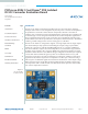


UG:301 vicorpower.com Applications Engineering: 800 927.9474 Page 3
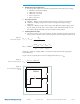
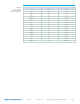
2. Default Pin Strap Configuration
a. Ensure the pin straps are in the following default locations before proceeding:
nENABLE = Not Used (enabled)
nTRIM_UP = Not Used
nTRIM_DN = Not Used
nOPT1 = Not Used
nOPT2 = Not Used
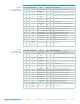
3. Pin Strap Functions
a. ENABLE – adding a strap on this pin will cause the converter to shut down.
b. TRIM_UP – Adding a strap in this location will adjust the output voltage
up by 10%.
c. TRIM_DN – Adding a strap in this location will adjust the output voltage down
by 10%. Only one strap can be connected at a time. If both trim straps are out,
the output voltage should be set to the model’s nominal output.
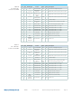
4. Trimming And Soft Start
a. For those customers who wish to trim to another voltage by changing the preset
trim resistors to another value, the trim equation shown in Figure 2 can be used:
R
low
=
(
–V
)
•
R
INT
(
–Vout
nom
)
+ V
desired
desired
R
high
=
(
–RSS
)
•
(
–Vout
nom
)
•
V
ERO
+ V •
V
ref
V
ref
[
(
–Vout
nom
) +
V
]
desired
desired
Where: R1 = Rlow R3 = Rhigh VERO = 4.9 and Vref can be found in the appropriate
model datasheet.
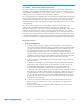
Figure 3 shows an equation for so start configuration where C7 = C
REF
C
REF
=
T
ssdesired
– 230 • 10
−6
23000
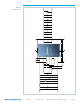
ENABLE
TRIM/SS
SGND
RSS
Rhigh
Rlow
VERO
Vref
PI31xx
10k
•
•
•
Figure 4.
PI31xx Trimming Equivalent
Circuit
Figure 2.
PI31xx Trim Equation
Figure 3.
PI31xx Soft Start Equation