VIPAC Array ™ POWER SYSTEMS CONFIGURATION GUIDE OFC
CONTENTS v i c o r p o w e r .
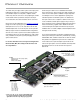
PRODUCT OVERVIEW The VIPAC Array is a highly flexible system of DC input, power VIPAC Arrays are ideal for use in distributed and modular building-blocks that can be configured with as many as four power systems where power density and reliable operation are user definable outputs on a low profile, coldplate chassis. critical.
Product Overview VA-A VA-E 2 MINIS I MICRO, 2 MINIS ● ● ● ● 3.62" x 6.69" x 0.78"[a] (92,0 x 170,0 x 19,8 mm) 1.3 lb (590 g) Single or dual output Up to 600 W ● ● ● ● 3.62" x 7.52" x 0.78"[a] (92,0 x 191,0 x 19,8 mm) 1.4 lb (635 g) Dual or triple outputs Up to 750 W total VA-B VA-F 1 MINI, 2 MICROS 4 MICROS ● ● ● ● 3.62" x 6.69" x 0.78"[a] (92,0 x 170,0 x 19,8 mm) 1.3 lb (590 g) Single, dual or triple outputs Up to 600 W total ● ● ● ● 3.62" x 7.52" x 0.76"[a] (92,0 x 191,0 x 19,3 mm) 1.
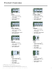
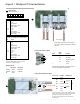
Input / Output Connections J1 Input Connector (View looking into J1) 1 11 10 20 J1 Pin# Funct. 1-4 5-7 8 9 10 11-13 14-17 18 19 20 – Vin +Vin NC / PR bus PE protective earth Neg. enable – Vin +Vin NC / PR bus PE protective earth Pos. enable 3 3 1 1 3 1 VA-J and VA-K configurations only (300 and 375 Vin single Maxi or single Mini) Pin# Funct. 1-3 4-6 7 8 9 10 11-13 14-16 17 18 19 20 – Vin +Vin NC NC / PR bus PE protective earth Neg. enable – Vin +Vin NC NC / PR bus PE protective earth Pos.
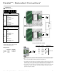
Parallel*** / Redundant Connections* Input Connector (View looking into J1) J1 10 20 1 11 Pin# Funct. 1-4 5-7 8 9 10 11-13 14-17 18 19 20 – Vin +Vin NC / PR bus PE protective earth Neg. enable – Vin +Vin NC / PR bus PE protective earth Pos. enable 1 J1 Funct. 1-3 4-6 7 8 9 10 11-13 14-16 17 18 19 20 – Vin +Vin NC NC / PR bus PE protective earth Neg. enable – Vin +Vin NC NC / PR bus PE protective earth Pos.
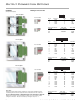
OUTPUT CONNECTION OPTIONS PlugMate Mating Connector Kits (Factory Installed Option) Micro PlugMate 1 5 4 8 Vicor P/N 25073 Pin # Function Pin # Function 1 2 3 4 +Vout +Vout –Vout –Vout 5 6 7 8 +Vout N/C SC –Vout Mating Connector Amp.
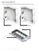
Mounting Options VIPAC Array with external, user supplied heat sink. VIPAC Array mounted to cabinet wall with thermal compound between VIPAC Array and cabinet wall. VIPAC Array mounted to custom thermal interface. Thermal compound v i c o r p o w e r .
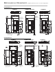
MECHANICAL DRAWINGS Coldplate thickness is 0.19'' ref for all configurations. Configuration A LugMates LugMates/Bus Bars PlugMates 0.78 19,9 0.78 19,9 0.81 20,6 0.9 0,04 Inches MM 0.197 5 3.94 100 3.86 98 3.62 92 3.228 82 #10-32 Stud fits 2 lugs min (Vicor P/N 23520) torque to 16 in. lbs. 4 places #10-32 Stud fits 2 lugs min (Vicor P/N 23520) torque to 16 in. lbs. 4 places Insulated Bus Bar (2 ) PL 1.54 39,1 2 1 2 1.35 34,3 6.69 170 6.299 160 3.76 95,4 3.189 81 1 1 1 1.35 34,3 1.
MECHANICAL DRAWINGS Configuration C LugMates LugMates/Bus Bars PlugMates 0.81 20,6 0.76 0.76 19,3 19,3 0.26 6,5 3.62 92 3.228 82 INCHES MM 3.84 98 #4-40 STUD FITS 2 LUGS MIN (VICOR P/N 23519) TORQUE TO 4 in. lbs. 6 PLACES 0.197 5 3.94 100 #4-40 STUD FITS 2 LUGS MIN (VICOR P/N 23519) TORQUE TO 4 in. lbs. 6 PLACES INSULATED BUS BAR (2 ) PL 3 2 2 0.70 17,8 0.72 18,3 0.72 18,3 2 2 3 0.70 17,8 6.69 170 6.299 160 3.80 96,5 3.81 96,8 0.72 18,3 1 5.36 136,2 1 1 0.70 17,8 5.
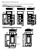
MECHANICAL DRAWINGS Configuration E LugMates LugMates/Bus Bars PlugMates 0.78 19,9 0.81 20,6 0.78 19,9 0.04 0,9 3.62 92 3.228 82 INCHES MM 0.197 5 3.86 98 #10-32 STUD FITS 2 LUGS MIN (VICOR P/N 23520) TORQUE TO 16 in. lbs. 4 PLACES 0.26 6,6 3.94 100 #10-32 STUD FITS 2 LUGS MIN (VICOR P/N 23520) TORQUE TO 16 in. lbs. 4 PLACES INSULATED BUS BAR (2 ) PL 1.54 39,1 3 2 3 1.35 34,3 5.43 137,8 1.54 39,1 2 2 1.35 34,3 2 7.52 191 7.126 181 3.15 3.05 77,5 79,9 121 1 1 0.70 17,8 0.
MECHANICAL DRAWINGS Configuration G and K LugMates PlugMates .78 0.81 20,6 19.9 3.62 92 1.35 34,3 1.14 28,9 #10-32 STUD FITS 2 LUGS MIN (VICOR P/N 23520) TORQUE TO 16 in. lbs. 2 PLACES 4.39 111,5 1 3.996 101,5 1.04 26,4 INCHES MM 0.26 6,7 1.54 39,1 4.7 119,4 0.31 7,8 1 INCHES MM 0.197 5 MOUNT (4) PL USING #8 FLAT HEAD SCREW (M4 FLAT HEAD SCREW) TORQUE TO 12 in. lbs. 3.228 82 0.197 5 Configuration H LugMates LugMates/Bus Bars .78 0.
TECHNICAL SUPPORT CONTACTS Vicor’s Technical support team is staffed with Applications Applications engineers ... Engineers to provide the product and application • Answer technical questions (by phone, fax, email, or the Vicor website). information and technical assistance customers need concerning Vicor products and power solutions. • Assist with component-based power system design.
Information furnished by Vicor is believed to be accurate and reliable. However, no responsibility is assumed by Vicor for its use. No license is granted by implication or otherwise under any patent or patent rights of Vicor. Vicor components are not designed to be used in applications, such as life support systems, wherein a failure or malfunction could result in injury or death. All sales are subject to Vicor’s Terms and Conditions of Sale, which are available upon request.