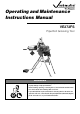
R Operating and Maintenance Instructions Manual VE272FS Pipe Roll Grooving Tool WARNING • Failure to follow instructions and warnings may result in serious personal injury, property damage or improper installation. • Before installing, operating, or servicing this tool, read and understand the instructions in this manual and all warning labels on the tool.
VE272FS READ THIS FIRST - HAZARD IDENTIFICATION 4 OPERATOR SAFETY INSTRUCTIONS 4 General 4 Tool Setup 4 Operating Tool 5 Tool Maintenance 5 INTRODUCTION 6 Power Drive 6 Power Requirements 6 TOOL NOMENCLATURE 7 RECEIVING TOOL 8 Container Contents 8 TOOL SETUP 9 PRE-OPERATION ADJUSTMENTS 14 Grooving Rolls 14 Pipe Preparation 14 Groovable Pipe Lengths 14 Short Pipe Lengths 14 Long Pipe Lengths 15 Roll Guard Adjustment 16 Pipe Stabilizer Adjustment 18 Groove Diameter Stop Adjustment 20 ACCESSORIES 32 Victaulic
VE272FS READ THIS FIRST - HAZARD IDENTIFICATION OPERATOR SAFETY INSTRUCTIONS Definitions for identifying the various hazard levels shown on warning labels or to indicate proper safety procedures in this Manual are provided below. This tool is designed only for roll grooving pipe. To accomplish this function requires some dexterity and mechanical skills, as well as sound safety habits.
VE272FS • Avoid dangerous environments. Don't use the machine in damp or wet locations. Don't use the tool on sloped or uneven ground or floor. Keep work area well illuminated. Allow sufficient space to operate tool and accessories properly and for others to pass safely. • Prevent back injury. During tool setup, it is recommended to use a lift to move and position the tool, as it cannot be safely handled by one person. Operating Tool • Inspect the equipment.
VE272FS INTRODUCTION DANGER ® ® The Victaulic Vic-Easy Series VE272FS is a semi-automatic hydraulic feed tool for roll grooving pipe to prepare it to receive Victaulic grooved pipe couplings. It is designed to roll groove pipe of various materials and wall thicknesses (see "Tool Rating and Roll Selection" charts). An external power drive is required and must be purchased separately.
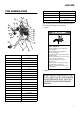
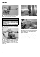
VE272FS TOOL NOMENCLATURE 1 i h 3 Item j k l g n e stabilizer roller v power drive stand w upper leg x adjusting legs The numbers in the illustration indicate the location of the following warning labels: m f Description u o • Label 1 p q r d s 2 b c t u a v w Grooving rolls can crush or cut fingers and hands. x Item Description a foot switch b lower roll c guard setting pad d pump support e pump handle f pump • Always unplug the power cord before adjusting guard.
VE272FS RECEIVING TOOL • Label 3 Failure to follow instructions and warnings can result in serious injury, property damage, or faulty installation. • Before installing, operating, or servicing this tool, read and understand the Operating Instructions and all warning labels on this tool. Victaulic® VE272FS tools are packed individually in sturdy containers, designed for use in reshipping the tool. • Always wear safety glasses and foot protection.
VE272FS carbon steel pipe. Rolls are marked with the size and part number and color coded for pipe material, for your convenience. For grooving to other specifications and other materials, see "Tool Rating and Roll Selection" charts. Grooving rolls for other specifications and other materials must be purchased separately. TOOL SETUP WARNING • Do not connect power until instructed otherwise. • Accidental start up of tool may result in serious personal injury. This tool is intended for field or shop setup.
VE272FS 5 Fully open the power drive chuck. (Consult power drive manufacturer's instructions.) WARNING 8 Tighten the chuck, making sure the jaws fit the drive shaft flats. • While the tool head assembly is on the power drive arms, without support legs installed, it is front heavy. Have someone push back on the tool head to prevent it from tipping over. • Failure to do so may result in serious personal injury. 6 Slide the tool head assembly fully onto the power drive arms.
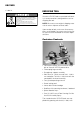
VE272FS 12 Release the lower legs by loosening the hex bolts. Turn the leg pads at the bottom until they rest flat on the floor. 11 Tighten the hex head bolts with a wrench. 13 Carefully level the tool front to back. Check tool levelness by placing level directly on top of the hydraulic ram as shown.
VE272FS 14 Tighten the hex head bolts with a wrench. The legs should now support the tool in a level position. 17 Hang the guard setting pad on the hook provided under the pump base. DANGER • To reduce the risk of electric shock, check the electrical source for proper grounding. • Always disconnect power before servicing or making any tool adjustments unless instructed otherwise. • Failure to do so may result in serious personal injury.
VE272FS duce clockwise rotation of the chuck, lower roll and pipe. 20 Depress foot switch and check chuck and lower roll direction and tool stability. If rotation is counterclockwise, move power drive switch to opposite position. If tool wobbles, make sure tool is mounted squarely in chuck and tool is level. If the wobble cannot be eliminated, the power drive support arms are bent or the power drive is damaged. Have the power drive repaired if wobble persists. 21 Disconnect power.
VE272FS PRE-OPERATION ADJUSTMENTS CAUTION ® Every Victaulic tool is checked, adjusted and tested at the factory prior to shipment. Before grooving, however, the following adjustments must be made in sequence to make sure of proper tool operation. • For maximum grooving roll life, remove foreign material and loose rust. • Foreign material such as coarse scale or dirt might interfere with or damage the grooving rolls or distort the groove.
VE272FS stead of roll grooving a 6.000 mm piece of pipe and a 198 mm piece of pipe, follow these steps: Length – [mm] O.D. [mm] Min. Max. 60,3 203 914 73,0 203 914 88,9 203 914 101,6 203 914 114,3 203 914 127,0 203 813 141,3 203 813 152,4 254 762 168,3 254 711 203,2 254 610 219,1 254 610 273,0 254 508/381 * 323,9 305 457/356 † * 508 mm long for aluminum, PVC and lightwall steel and stainless steel. 381 mm long for Sched.
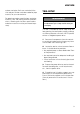
VE272FS Tool Centerline Pipe angle exaggerated for clarity 0° to ¹⁄₂° Max. (0 to 50,8 mm) Pipe Centerline 6 m Pipe Figure 2 - Tracking angle WARNING • Pipe stand location will affect pipe tracking. • Incorrect pipe stand position may cause the pipe to be pushed out of rolls and fall. • Failure to position pipe and pipe stand in accordance with the figures shown may result in serious personal injury or property damage.
VE272FS 3 Set groove diameter stop to pipe size and schedule/thickness to be grooved. To do this, back off the depth adjuster lock, align the depth adjuster with the proper diameter and thickness. Lock the depth adjuster in position with the depth adjuster lock. See "Groovable Pipe Lengths" instructions and cautionary information. WARNING • Grooving rolls can crush or cut fingers and hands. • Loading and unloading pipe will place your hands close to the rollers.
VE272FS 7 Pump upper roll down into firm contact with the pipe. 10 Remove the guard setting pad. Store the pad back on the hook provided. Pipe Stabilizer Adjustment (applies only to tools equipped with the optional stabilizer) 8 Remove the guard setting pad from its storage hook. Hold the guard setting pad firmly down against the pipe and push it under the adjustable guards flush against the red plate. The Series VE272FS pipe stabilizer is designed to pervent sway of 219,1 - 323,9 mm pipe.
VE272FS 3 Insert a piece of pipe of the correct size and schedule/thickness to be grooved over the lower roll with the pipe end against the lower roll backstop flange. 5 Make sure guards are properly adjusted. Refer to "Roll Guard Adjustment". 6 Advance stabilizer roller inward with the handwheel until the roller lightly contacts the pipe, then tighten locking handle. CAUTION 4 Close hand pump valve and pump upper roll down into firm contact with the pipe.
VE272FS For your convenience, a "C" dimension chart for steel pipe is also on the tool. NOTICE To perform the following adjustments, use several short scrap sections of pipe (but not shorter than what is recommended in the "Groovable Pipe Lengths" table) of the proper material, diameter and thickness to be grooved. To achieve proper diameter: 1 Determine the size and thickness of pipe to be grooved. See "Pipe Dimensions" to determine proper schedule.
VE272FS grooved, place the pipe over the lower roll with the pipe end against the lower roll backstop flange. the groove. Average reading must equal the required groove diameter specification. WARNING CAUTION • Grooving rolls can crush or cut fingers and hands. • Always disconnect power before servicing or making any tool adjustments unless instructed otherwise. • Be sure guard is properly adjusted before grooving pipe. • Keep hands away from grooving rolls and stabilizer wheel.
VE272FS GROOVING OPERATION DANGER CAUTION • Victaulic® Series VE272FS tools are designed ONLY for roll grooving pipe of the sizes, materials and wall thicknesses outlined under "Tool Rating and Roll Selection". • Grooving pipe other than that recommended will result in improper pipe end configuration or improper groove dimensions for applying Victaulic products.
VE272FS WARNING • Grooving rolls can crush or cut fingers and hands. • Always disconnect power before servicing or making any tool adjustments unless instructed otherwise. • Always groove pipe in a clockwise direction only. • Be sure guard is properly adjusted before grooving pipe. • Keep hands away from grooving rolls and stabilizer wheel. • Never reach inside pipe end or across the tool or pipe during operation. • Never groove pipe shorter than what is recommended (See "Groovable Pipe Lengths").
VE272FS NOTICE Do not pump too fast, but at a rate sufficient to groove the pipe and maintain audible moderate-to-heavy load on the gear motor. 10 Let the grooving continue until the depth adjuster lock comes into full, firm contact with the underlying surface. Continue pipe rotation for several revolutions to ensure groove completion. NOTICE Groove diameter should be correct for the diameter and wall thickness of pipe for which it was set under "Groove Diameter Stop Adjustment".
VE272FS ROLL CHANGING WARNING • Always disconnect power before servicing or making any tool adjustments unless instructed otherwise. • Accidental start up of tool may result in serious personal injury. NOTICE Victaulic® Series VE272FS roll grooving tools are designed for fast, easy grooving. Rolls accommodate several pipe sizes (refer to "Tool Rating and Roll Selection") eliminating the need for frequent roll changes.
VE272FS WARNING Hammering rolls can cause serious personal injury due to fragmentation. • Always wear eye protection. • Always use supplied aluminum wedge for roll removal. • Always use soft faced hammers with aluminum wedge. • Never strike rolls directly for any reason. 2 Remove the upper roll assembly. Store in a clean place. 5 Remove nut, washer and roll and store in a clean place. NOTICE Be careful not to lose the Woodruff keys. They should remain in the lower shaft.
VE272FS 2 While upper roll is removed from tool, inspect the roller bearing inside for contamination, proper lubrication and movement. Also inspect guards for wear and freedom of adjustment. Make repairs/replacements as necessary. 4 Insert upper roll bolt and tighten securely with a wrench. 5 Lubricate upper roll bearing. Refer to "Maintenance" section for additional information. 3 Carefully slide desired upper roll assembly onto upper shaft with red plate facing out.
VE272FS MAINTENANCE General This manual provides information to permit the operator of Victaulic® roll grooving tools to keep his equipment in top operating condition and to guide him in making repairs when it becomes necessary. 2 Install flat washer and large nut on threaded arbor stud, in front of lower roll, and tighten securely with a wrench. Replacement parts, applicable only to these tools, should be ordered from Victaulic to ensure proper operation of the tool.
VE272FS Hydraulic Systems The level of the hydraulic fluid in the pump must be checked every six months or if pumping feels spongy. Filling and Checking 1 Open pump release valve fully by turning counterclockwise. 2 Grease main shaft bearings at fittings provided as shown. Use a No. 2EP Lithium base grease. 2 Remove pump and pump support from tool base. 3 Loosen, but do not remove the hydraulic fill plug/dipstick at the back end of the pump.
VE272FS dipstick, remove cap; oil should be approximately 15-25 mm from the end. Air Bleeding 1 To bleed air from the system, hold the entire pump above the hydraulic cylinder. Close the pump release valve by turning clockwise. Open fill plug one full turn. Recommended Lubricants Bearing and Slide Grease General Purpose E.P. Lithium Base Grease. 2 Pump the pump handle several strokes to build pressure. 3 Open release valve by turning counterclockwise and allow air to escape.
VE272FS Manufacturer Product Mobil Oil Corp. Mobil DTE 24 Pennzoil Prod. Co. AW 32 Hyd. Oil/Penreco Oil 32 Shell Oil Co. Tellus 32 Sun Refining Survis 706, 816 WR Texaco Inc. Rando Oil HD 32 PARTS ORDERING INFORMATION When ordering parts, the following information is necessary for Victaulic Europe to process the order promptly and send the correct part(s): • Tool Model Number: VE272FS • Tool Serial Number. The serial number can be found stamped onto the tool body.
VE272FS ACCESSORIES Ridgid® 300 Power Drive Victaulic Adjustable Pipe Stand VAPS112 Victaulic Model VAPS 112 (art. code: R000112PS0), a portable, adjustable, roller type, four-leg pipe stand for use with Victaulic roll grooving tools, is available from Victaulic Europe. Ball transfer rollers, adjustable for pipe from 26,9 - 323,9 mm, will accommodate linear and rotational movement. Turnstile design permits easy swivel for grooving both pipe ends. Contact Victaulic Europe for details.
VE272FS of 219,1 mm and above. Contact Victaulic Europe for details.
VE272FS TROUBLESHOOTING Problem Pipe will not stay in grooving rolls. Pipe stops rotating during grooving. Possible Cause Solution Incorrect pipe positioning. See Pipe Support section. Improper manual grooving technique. See "Grooving Operation" - Grooving Short Pipe Lengths section. Power Drive running counterclockwise See "Tool Setup". Rust or dirt has built up on lower roll. Remove accumulation from lower roll with stiff wire brush. Rust or dirt is excessively heavy inside the pipe end.
VE272FS TOOL RATING AND ROLL SELECTION Standard and "ES" Rolls - Color Coded Black 1 2 3 4 Nominal Wall Thickness Dimensions - [mm] O.D. [mm] Aluminum Pipe PVC Plastic Pipe Min. Steel Pipe Max. Stainless Steel Pipe Min. Max. Min. Max. Min. Max.
VE272FS Rolls for Stainless Steel Pipe† (RX Rolls) - Color Coded Silver Nominal Wall Thickness - [mm] O.D. [mm] Sched. 5S Sched. 10S 60,3 1,70 2,80 73,0 2,10 3,00 88,9 2,10 3,00 101,6 2,10 3,00 114,3 2,10 3,00 141,3 2,80 3,40 168,3 2,80 3,40 219,1 2,80 3,80 273,0 3,40 4,20 323,9 4,00 4,60 RX Roll Nos.
VE272FS ROLL GROOVE SPECIFICATIONS Steel Pipe and All Materials Grooved with Standard and RX Rolls B A B OD T C D 1 2 3 4 O.D. - [mm] 5 6 7 Dimensions - [mm] Tolerance Groove Width B ±0,76 Groove Dia. C Basic Tolerance Grv. Depth D (ref.) Min. Wall Thk. T Max. Flare Dia.
VE272FS COLUMN 2: Gasket seat – The pipe surface shall be free from indentations, roll marks, and projections from the end of the pipe to the groove, to provide a leak-tight seal for the gasket. All loose paint, scale, dirt, chips, grease and rust must be removed. It continues to be Victaulic’s first recommendation that pipe be square cut. When using beveled pipe contact Victaulic for details. Square cut pipe must be used with FlushSeal® and EndSeal® gaskets.
VE272FS Drawn Copper Tubing B A B OD T C D 1 2 3 O.D. - [mm] 4 5 6 7 Dimensions - [mm] Basic Tolerance Gasket Seat A ±0,76 Groove Width B +0,76/-0,00 Groove Diame- Groove Depth ter C +0,00 (ref.) D Min. Wall Thk. T Max. Flare Dia.
VE272FS Steel Pipe and All Materials Grooved with "ES" Rolls B A B OD T C D 1 2 3 4 O.D. - [mm] 5 6 7 Dimensions - [mm] Tolerance Basic + - Gasket Seat A +0,00/-0,51 Groove Width B Groove Diameter C Basic Tol. -0,00 Basic Tol. +0,00 Groove Depth (ref.
VE272FS PIPE DIMENSIONS Seamless and Welded Steel Pipe† Nominal Wall Thickness - [mm] O.D. [mm] Sched. 5S Sched. 10S Sched. 10 Sched. 20 Sched. 30 Sched. 40 Sched. STD Sched.
how to contact Victaulic Europe R Victaulic Europe Prijkelstraat 36 B-9810 Nazareth Belgium tel: +32-9-381.15.00 fax: +32-9-380.44.38 e-mail: viceuro@victaulic.be www.victaulic.com/europe Victaulic Europe subsidiaries Victaulic Polska R Ul. Niepodleglosci 8 66530 Drezdenko Poland Victaulic Espana R Avda.