REACH-IN, ROLL-IN, ROLL-THRU & PASS-THRU WARMERS OWNERS MANUAL (For “Quick Navigation”, Click On Topics or Sections Highlighted In Blue) ★ DESCRIPTION ★ INSTALLATION ★ OPERATION ★ MAINTENANCE ★ PARTS LISTS ★ WIRING DIAGRAMS
Warranty (Continental USA Only) The Seller warrants to the original purchaser, equipment manufactured by Seller to be free from defects in material and workmanship for which it is responsible. The Seller's obligation under this warranty shall be limited to replacing or repairing at Seller's option, without charge, F.O.B.
RETAIN THIS MANUAL FOR FUTURE REFERENCE NOTICE Victory (Manufacturer) reserves the right to change specifications at any time. IMPORTANT Warranty Registration Card Enclosed. Failure to Properly Register Equipment Can Void Warranty !!!! NOTICE Please Read The Entire Manual Carefully Before Installation.
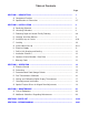
Table of Contents Page SECTION 1 - DESCRIPTION .................................................................................... 1 A. Component Function ................................................................................. 1 B. Specifications & Dimensions ..................................................................... 2-7 SECTION 2 - INSTALLATION .................................................................................. 8 A. Receiving Shipment ...........................
SECTION 1-DESCRIPTION SECTION 1-DESCRIPTION SECTION 1 DESCRIPTION A. Component Function 1. Doors. Each door has a cylinder lock, recessed handle and self-adjusting magnetic gasket. a. Door Size. The doors are full length and half length. *Note: There are only full length doors available for Roll-In and Roll-Thru cabinets. b. Door Type. The doors are stainless steel. c. Door Hinges. Cam-lift hinges give the doors their self-closing features. d.
SECTION 1-DESCRIPTION SECTION 1-DESCRIPTION B. Specifications: Reach-In & Pass-Thru Warmer Specifications *Note: Approx. Pass- Thru weights, add 15 % CHARACTERISTICS Width,Overall ONE SECTION Reach-In Pass-Thru 26-1/2” 26-1/2” TWO SECTION Reach-In Pass-Thru 52-1/8” 52-1/8” Depth,Overall(incl. handles) 36-1/8” 39-7/8” 36-1/8” 39-7/8” Height,Overall(incl. adj.
SECTION 1-DESCRIPTION SECTION 1-DESCRIPTION Reach-In & Pass-Thru Dimension Drawings: We reserve the right to change specifications and product design without notice. Such revisions do not entitle the buyer to correspond changes, improvements additions or replacements for previously purchased equipment.
SECTION 1-DESCRIPTION Specifications: SECTION 1-DESCRIPTION Extra Wide Warmer Specifications *Note: Approx. Pass- Thru weights, add 15 % CHARACTERISTICS Width,Overall ONE SECTION Reach-In Pass-Thru 31-1/4” 31-1/4” TWO SECTION Reach-In Pass-Thru 58-3/8” 58-3/8” Depth,Overall(incl. handles) 36-1/8” 39-7/8” 36-1/8” 39-7/8” Height,Overall(incl. adj.
SECTION 1-DESCRIPTION SECTION 1-DESCRIPTION Extra Wide Reach-In & Pass-Thru Dimension Drawings: We reserve the right to change specifications and product design without notice. Such revisions do not entitle the buyer to correspond changes, improvements additions or replacements for previously purchased equipment.
SECTION 1-DESCRIPTION SECTION 1-DESCRIPTION Specifications: Roll-In Warmer Specifications *Note: Approx. Pass- Thru weights, add 15 % Width,Overall ONE SECTION Roll-In Roll-Thru 36-1/2” 36-1/2” TWO SECTION Roll-In Roll-Thru 68-7/8” 68-7/8” Depth,Overall(incl. handles) 36-1/8” 39-7/8” 36-1/8” 39-7/8” Height,Overall(incl. adj.
SECTION 1-DESCRIPTION SECTION 1-DESCRIPTION Roll-In & Roll-Thru Dimension Drawings: We reserve the right to change specifications and product design without notice. Such revisions do not entitle the buyer to correspond changes, improvements additions or replacements for previously purchased equipment.
SECTION 2-INSTALLATION SECTION 2-INSTALLATION SECTION 2 INSTALLATION A. Receiving Shipment 1. Removing Doors. (Refer to Figure 2-1) Upon arrival, examine the exterior of the shipping carton for any signs of rough handling. It is advisable that the shipping carton be partially removed, in order to examine for any possible concealed damages which might have occurred during shipment. a. Open door to approximately 90° b.
SECTION 2-INSTALLATION SECTION 2-INSTALLATION 3. Hinges and Lock Keeper a. Refer to Figure 2-2. To remove the hinge base from the cabinet fascia, unscrew the three machine screws. On the upper hinge, you will notice a light switch with six inch red lead wires. Tape switch to interior door jamb. Do not remove wires. When reinstalling upper hinge, nest switch into bottom of base and fasten carefully to fascia. Figure 2-3 Lock Keeper D.
SECTION 2-INSTALLATION SECTION 2-INSTALLATION Tilt the cabinet in one direction approximately eight inches and block it securely to keep it from falling. Use several pieces of 2” x 4” lumber or other suitable material. Screw the two left right legs in until snug with brace. Repeat this procedure to install the other legs. WARNING DO NOT , Under Any Circumstances, Lay Your New Equipment Down On Either The Back, Front or Sides F. Leveling Cabinet must be leveled when installed.
SECTION 2-INSTALLATION SECTION 2-INSTALLATION b. Steel Rod Type Pan Slide Racks (Refer to Figure 2-7) Steel rod type pan slide racks are also available. They are designed to accommodate 18” x 26” sheet pans as follow: ● Bottom Support Pan Slide Rack on 2” centers ● Lip Support Pan Slide Rack on 1-1/2” centers Uprights for mounting the steel rod type pan slide racks are factory installed.
SECTION 2-INSTALLATION SECTION 2-INSTALLATION I. Roll-In Unit Grouting and Sealing 4. Using a wide blade putty knife, taper the grout to a feather edge. NOTE: It is an N.S.F. requirement that Roll-In models are sealed to the floor upon installation. Note: The procedure for setting and grouting the two section model illustrated below is typical and also applies to one sections. WARNING CARE SHOULD BE TAKEN TO AVOID GOUGING OR MARRING SURFACE OR EDGES OF ALUMINUM RAMP. 1.
SECTION 2-INSTALLATION SECTION 2-INSTALLATION L. Warranty Cards Locate the warranty cards at the front of this manual. Fill out all three cards (“Factory Record Card”, “Distributor’s Record Card” and “Customer’s Record Card”) and mail the Factory and Distributor’s cards as directed. The Customer’s card must be retained by the customer.
SECTION 3-OPERATION SECTION 3-OPERATION SECTION 3 OPERATION A. Electrical Control The temperature of the Victory Warming Cabinet is maintained by means of a thermostat which can be adjusted to give the desired temperature 80°F -180°F. The thermostat setting determines the temperature at which the heating elements are de-energized by the control. The dial thermometer indicates the approximate temperature within the cabinet.
SECTION 3-OPERATION SECTION 3-OPERATION Some foods can be kept in good condition much longer than others, and certain foods cannot be satisfactorily kept at all in any manner. French fried potatoes, roasts, waffles and similar foods, where the outside must be crisp and centers steaming hot, must be prepared immediately before serving.
SECTION 3-OPERATION SECTION 3-OPERATION D. Dial Thermometer Calibration: 1. Check cabinet temperature by using an accurate hand held dial or digital thermometer. 2. Look at the dial thermometer on the cabinet grille, if it matches the thermometer test meter (+ or -1°F)do not adjust. 3. It it does not match, remove the dial thermometer lens with a small screwdriver. 4. To adjust the temperature needle, insert a small screwdriver in the slotted screw on the needle. 5.
SECTION 3-OPERATION SECTION 3-OPERATION E. Instructions for Setting and Calibrating Digital Display Thermometer: Victory’s digital display thermometers have a sensing range of -40°F to 220°F (-40°C to 105°C) which allows it to be used in a wide variety of applications. Setting the control for proper application is accomplished by installing the jumper on the “HI” or “LO” pin position. “HI” for Refrigerators and Freezers, and “LO” for Warming Cabinets. 1.
SECTION 3-OPERATION SECTION 3-OPERATION F. Door Adjustment Instructions: Victory has provided a unique self-closing hinge assembly for majority of the cabinets that consist of hinged doors. Instead of having to deal with complex methods for good door alignment and/or proper door gasket sealing, the features on the hinge assembly (PN 10685101) makes the task very easy. When adjustment of the door gasket seal or alignment is desired, fine-tuning can be accomplished with the Adjusting Plate (pn 50520104).
SECTION 3-OPERATION SECTION 3-OPERATION G. Special Feature Shims for Hinged Door Adjustments: There are a couple of special feature shims that assist with the adjustment of hinged doors using the self-closing hinge assembly (pn 10685101). These items can be used as a second or third option if additional adjustment is required. Refer to the shim descriptions below and their purpose. 1.
SECTION 4-MAINTENANCE SECTION 4-MAINTENANCE SECTION 4 MAINTENANCE A. Care of Equipment The cabinet should be cleaned each night. In doing this, avoid using an excessive amount of water. A damp cloth and any good grease solvent, or soap, should remove any food which has been accidentally spilled into the cabinet. Turn off power with thermostat switch when through using the unit for the day.
SECTION 5-PARTS LIST SECTION 5-PARTS LIST SECTION 5 PARTS LISTS 21
SECTION 5-PARTS LIST SECTION 5-PARTS LIST 1 & 2 Section Standard, Extra Wide, Roll-In & Half Door “Series 6 & 7” Warmers Parts Lists (*Note: For other parts not presented on the list, please consult factory with cabinet model & serial number) Part No.
SECTION 5-PARTS LIST SECTION 5-PARTS LIST 1 & 2 Section Standard, Extra Wide, Roll-In & Half Door “Series 6 & 7” Warmers Parts Lists (*Note: For other parts not presented on the list, please consult factory with cabinet model & serial number) Part No.
SECTION 6-WIRING DIAGRAMS SECTION 6-WIRING DIAGRAMS SECTION 6 WIRING DIAGRAMS 24
SECTION 6-WIRING DIAGRAMS SECTION 6-WIRING DIAGRAMS 1 & 2 Section Warmer 208/230V (Standard) 25
SECTION 6-WIRING DIAGRAMS SECTION 6-WIRING DIAGRAMS 1 & 2 Section Warmer 208/230/115V (Optional) “End Of Section, Click Here For Table Of Contents”
VICTORY REFRIGERATION 110 Woodcrest Road Cherry Hill, NJ 08003 Phone (856) 428-4200 Fax (856) 428-7299 Website: www.victory-refrig.com E-Mail: parts@victory-refrig.com parts.order-entry@victory-refrig.com or service@victory-refrig.com Manual Part Number: 50785901 Rev: 03 Print Date: 4/30/02 Price: $15.00 Website: www.agafoodservice.