Cvr_9920340 2/1/06 3:53 PM Page 1 2005-2006 HAMMER TM 2006 VEGAS JACKPOT & NESS SIGNATURE SERIES VEGAS JACKPOT SERVICE MANUAL TM 2005-2006 HAMMER / 2006 VEGAS JACKPOT TM TM SERVICE MANUAL 9920340 PN 9920340 Printed in USA 31
005-2006 Hammert 2006 Vegas Jackpott 2006 Ness Signature Series Vegas Jackpott SERVICE MANUAL Part Number 9920340 Foreword This manual is designed primarily for use by Victory service technicians in a properly equipped shop and should be kept available for reference in the shop area. All references to left (LH) and right (RH) side of the motorcycle are from the operator’s perspective when seated in a normal riding position.
GENERAL & MAINTENANCE GENERAL 1 MAINTENANCE 2 3 4 5 6 FRAME/BODY/EXHAUST LUBRICATION & COOLING FUEL SYSTEM/FUEL INJECTION ELECTRICAL CHASSIS ENGINE ENGINE REMOVAL & INSTALLATION 7 CYLINDER & PISTON 8 CLUTCH, PRIMARY, & SHIFT 9 TRANSMISSION & CRANKSHAFT 10 DRIVE LINE 11 FRONT WHEEL & SUSPENSION 12 REAR WHEEL & SUSPENSION 13 TIRES 14 BRAKES 15 CHARGING SYSTEM 16 IGNITION SYSTEM & BATTERY 17 ELECTRIC STARTER 18 LIGHTING & INSTRUMENTATION 19 CYLINDER HEAD & VALVES
GENERAL INFORMATION CHAPTER 1 GENERAL INFORMATION 1 GENERAL INFORMATION . . . . . . . . . . . . . . . . . . . . . . . . . . . . . . . . . . . . . . . . . . . . . . 1.3 TRADEMARKS . . . . . . . . . . . . . . . . . . . . . . . . . . . . . . . . . . . . . . . . . . . . . . . . . . . . . . . . . 1.3 SERVICE RULES . . . . . . . . . . . . . . . . . . . . . . . . . . . . . . . . . . . . . . . . . . . . . . . . . . . . . . . 1.3 SAFETY INFORMATION. . . . . . . . . . . . . . . . . . . . . . . . . . . . . . . . .
GENERAL INFORMATION WIRE HARNESS CONNECTOR LOCATIONS. . . . . . . . . . . . . . . . . . . . . . . . . . . . . . 1.24 TOP VIEW . . . . . . . . . . . . . . . . . . . . . . . . . . . . . . . . . . . . . . . . . . . . . . . . . . . . . . . . . . . 1.24 LEFT SIDE VIEW. . . . . . . . . . . . . . . . . . . . . . . . . . . . . . . . . . . . . . . . . . . . . . . . . . . . . . 1.25 RIGHT SIDE VIEW . . . . . . . . . . . . . . . . . . . . . . . . . . . . . . . . . . . . . . . . . . . . . . . . . . . . 1.
GENERAL INFORMATION 1 GENERAL INFORMATION TRADEMARKS Victory acknowledges the following products mentioned in this manual: FLEXLOC, Registered Trademark of SPS Technologies Loctite, Registered Trademark of the Loctite Corporation STA-BIL, Registered Trademark of Gold Eagle Nyogel, Trademark of Wm. F. Nye Co. Fluke, Registered Trademark of John Fluke Mfg. Co. Mity Vac, Registered Trademark of Neward Enterprises, Inc.
GENERAL INFORMATION SAFETY INFORMATION UNDERSTANDING SAFETY LABELS & INSTRUCTIONS READ AND BECOME FAMILIAR WITH ALL WARNING AND CAUTION SYSMBOLS AND STATEMENTS LISTED BELOW AND IN THE TEXT OF THIS MANUAL BEFORE YOU BEGIN WORK. DANGER, WARNINGS, & CAUTION SYMBOLS This is the safety alert symbol. When you see this symbol on your machine or in this manual, be alert to the potential Gasoline is extremely flammable and explosive for personal injury. Your safety is involved! under certain conditions.
GENERAL INFORMATION 1 REFINISHING VICTORY TOUCH-UP AND REFINISHING PAINT Service Paint products are available in three different sizes and applications. Some paint colors require up to 3 components to create a color. Prices subject to change without notice. Dealer is responsible for freight on paint and paint products. .6 ounce bottle: (Order Multiple of 2) For brush touch-up of small nicks. 10 ounce aerosol can: (Order Multiple of 2) Apply light even coats for best results.
GENERAL INFORMATION PAINT COLORS BY MODEL NOTE: Refer to www.polarisdealers.com for more information. NOTE: The 9th letter of the model number designate the color. “P” in the 10th position indicates Premium model. Refer to page 1.7 for paint color code. Detailed paint ordering information is available on the dealer web site at News, Forms & Links / Pure Polaris / Paint Codes & Part Numbers.
GENERAL INFORMATION 1 PAINT COLOR CODES PAINT COLOR - 2005 and 2006 PAINT CODE NOTES Cruiser Black (PHAT) P-266 Indy Red P-293 Flame Yellow P-388 Turbo Silver P-445 Paint kits require base coat with a topcoat of Clear Metallic (CM) Cosmic Sunburst P-446 Clear coat (C) required Toxic Green Pearl P-491 Aerosols, Kits, and Touch-Ups require a white base (WU). Toxic Green Pearl.
GENERAL INFORMATION VEHICLE INFORMATION VEHICLE IDENTIFICATION NUMBER (VIN) See “VIN NUMBER LOCATION” on page 1.9 for location on the vehicle.
GENERAL INFORMATION 1 VIN NUMBER LOCATION A The vehicle identification number (A) is stamped on the right side of the steering head. MODEL NUMBER LOCATION B The model label (B) is located on the left side of the steering head. ENGINE NUMBER LOCATION The engine number label (C) is attached to the horizontal crankcase surface (2005 Hammer) or stamped into the right crankcase boss (D) (2006 models). The label or stamping identifies the engine model and serial number.
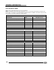
GENERAL INFORMATION PUBLICATIONS & TECHNICAL LITERATURE PUBLICATION PART NUMBERS The following chart lists the part numbers for Owner’s Manuals, parts books, and parts microfiche. OTHER VICTORY PUBLICATIONS Year / Model Publication Part Numbers U.S.
GENERAL INFORMATION 1 BREAK IN PERIOD BREAK-IN PROCEDURE There is never a more important period in the life of a new Victory motorcycle than the period between zero and 500 miles (805 km). A Victory motorcycle is manufactured using the best possible materials and manufacturing techniques, but the final machining process is the break-in. During break-in period, many parts in the engine wear and polish to correct operating clearances.
GENERAL INFORMATION EXHAUST EMISSION CONTROL Victory Motorcycles have an electronic engine management system which controls fuel delivery and ignition timing to control hydrocarbon and carbon monoxide emissions. Except for TPS adjustments as required by the Periodic Maintenance Interval Table on page 2.11, or if components are replaced that affect idle speed, no adjustments should be made to the system. NOISE EMISSION CONTROL SYSTEM Tampering with Noise Control Systems is Prohibited.
GENERAL INFORMATION 1 INSTRUMENTS 1. Speedometer 2. Tachometer 3. Odometer / 4. Trip Odometer 5. Reset Button JACKPOT / NESS JACKPOT 6. Overdrive Light (Tachometer equipped only) HAMMER SPEEDOMETER (1) The speedometer receives an input signal from the speed sensor located on top of the crankcase behind the rear cylinder. Pulse signals from the speed sensor are converted inside the speedometer to speed and distance outputs in miles (kilometers in Canada).
GENERAL INFORMATION INDICATOR LIGHTS 7 1 2 4 3 5 6 Table 1-1: # Symbol / Function NEUTRAL INDICATOR 1 HEADLAMP HIGH BEAM 2 Operation The neutral indicator illuminates when the transmission is in Neutral, and the ignition key is ON. The headlamp high beam indicator illuminates when the headlamp switch is set to High and the ignition key is ON.
GENERAL INFORMATION 1 SPECIAL SERVICE TOOLS GENERAL & PRECISION MEASUREMENT TOOL PART NUMBER Bearing & Seal Driver Set PV-43558 Bore Gauge Set, 50-100mm PV-3017 Decal, Service Bulletin Completion Dial Caliper (Metric, 0-150mm) Dial Caliper (Electronic Conversion. English 0-6” / Metric 0-150mm) Dial Indicator, Adjustable (Metric. 10mm travel) 7170107 (Order from Victory Parts Dept.) PV-26900-7 PV-39776 PV-26900-12 Dial Indicator Stand, Flexible.
GENERAL INFORMATION ENGINE, CLUTCH, & TRANSMISSION TOOL PART NUMBER Clutch Hub Holding Tool PV-43518 Clutch Shaft Holder PV-45028 Clutch Shaft Bearing Support (for clutch shaft installation) PV-47331 Crankcase Assembly Tool (Same as Mainshaft / Crankcase Installer) Crankcase Assembly Tool Adaptor PV-46299 (Must be used with PV-45030) and Adaptor (Extension) PVX-47429 PVX-47429 Crankshaft Bearing Protector PV-47207 Crankshaft Rotation Socket PV-46988 Crankcase Separator (Crankcase Removal) PV-
GENERAL INFORMATION 1 WHEEL & TIRE TOOL PART NUMBER Air Pressure Gauge Commercially Available Tire Bead Breaker ( May be part of the tire removal equipment being used) Commercially Available Tire Mounting Lubricant Commercially Available Tire Removal Equipment Commercially Available Rim Protector PV-43536 Wheel Balancing/Truing Stand TBA FUEL SYSTEM & FUEL INJECTION SPECIAL TOOLS- FUEL SYSTEM/ FUEL INJECTION PART NUMBER Victory/Polaris Diagnostic Tool Kit w/ Diagnostic Software PV-46085 (
GENERAL INFORMATION TRANSPORTING AND SECURING THE MOTORCYCLE GENERAL GUIDELINES If you must transport the motorcycle or secure it to a lift table: • Use a truck, trailer, or lift table designed or equipped properly for motorcycles. Review truck, trailer or lift manufacturer’s recommendations. • Do not tow the motorcycle with another vehicle, as towing will impair the motorcycle’s steering and handling, which can cause a loss of control.
GENERAL INFORMATION 1 ROUTING DIAGRAMS WIRE HARNESS - LEFT REAR FRAME Tie Strap Includes: Frame Tube Main Bundle Regulator / Rectifier Harness Crankshaft Position Sensor (CPS) Harness Tie Strap Includes: Starter Cable Regulator / Rectifier Harness Crankshaft Position Sensor (CPS) Harness ! Starter cable to be routed on outside of CPS and Voltage Regulator wiring Rear Brake Light Switch Oil Pressure Switch = Apply Dielectric Grease P/N 2871329 1.
GENERAL INFORMATION WIRE HARNESS - RIGHT REAR FRAME MAP Sensor Tie Strap: Place between fuel pump harness and main harness clip Gear position switch harness connector 1.
GENERAL INFORMATION 1 WIRE HARNESS - RIGHT SIDE Harness Route OBD ll Diagnostic Port Fuse Box Speed Sensor Harness Clip Speed Sensor Throttle Position Sensor (TPS) Horn Front Injector Jumper Gear Position Switch 1.
GENERAL INFORMATION WIRE HARNESS - UNDER SEAT Rear Harness Connector Chassis Ground ! Do not ground other items to this terminal ECM Connector (Access by removing battery box) 1.
GENERAL INFORMATION 1 REAR FENDER Refer to Chapter 3 for fender removal Stop / Tail Lamp Connectors Secure wires in guides Turn Signal Connectors License Plate Lamp Connectors Secure wires in guides 1.
GENERAL INFORMATION WIRE HARNESS CONNECTOR LOCATIONS TOP VIEW Indicator Lights Front Left Turn Signal Left Hand Controls Inside Headlamp Speedometer Front Right Turn signal Right Hand Controls Tachometer (or Accy Tach) Horn = Apply a light film of Dielectric Grease 2871329 Regulator/Rectifier Crankshaft Position Sensor (CPS) Dart Voltage Regulator Battery Positive (+) Circuit Breaker Power Out Starter Relay (Solenoid) Chassis Ground ! Do not add other grounds here Oil Pressure Battery Negative B
GENERAL INFORMATION 1 LEFT SIDE VIEW = Apply a light film of Dielectric Grease 2871329 Air Temperature Sensor Front Fuel Injector Jumper Ignition Coils High Intensity Discharge HID Ballast Power HID Ballast Output Horn Chassis Ground ! Do not add other grounds here Ignition Switch Output Oil Temperature Sensor (Rear cylinder head LH side) Starter Relay Tie Strap Speed Sensor (Rear top of Crankcase) Crank Position Sensor (CPS) On front left primary cover Engine Control Module (ECM) Engine Ground (
GENERAL INFORMATION RIGHT SIDE VIEW = Apply a light film of Dielectric Grease 2871329 Harness Clips (to frame) Air Temperature Sensor Horn Rear Fuel Injector Ignition Switch Starter Solenoid Speed Sensor Crankshaft Position Sensor (CPS) Gear Position Switch Engine Ground Tie Strap Route starter motor cable outside of these Regulator/Rectifier Rear Brake Light Switch 1.
GENERAL INFORMATION 1 FUEL TANK VENT AND DRAIN HOSE ROUTING 2005 HAMMER - 49 STATE, CANADA, UK NOTE: On 2005 Hammer 49 State, Canada, or UK models, the fuel cap is vented. Drain hose fitting for cap area on left side of tank Clamp 22 in. lbs. (2.5 Nm) Tanks with a single hose (water drain) must have a vented fuel cap. See Chapter 5 to test cap vent. Tie Strap. Do not crimp. A 49 State, Canada, UK Models One side of “Y” connection is plugged or may be a straight single connection. Tie Strap.