ENGLISH MultiPlus 2kVA 120V rev 05 - 01/2022
MultiPlus 2kVA 120V Table of Contents 1. IMPORTANT SAFETY INSTRUCTIONS - SAVE THESE INSTRUCTIONS ................................................... 1 2. Description ............................................................................................................................ 3 2.1. General ....................................................................................................................... 3 2.2. Battery charger ..............................................................
MultiPlus 2kVA 120V 1. IMPORTANT SAFETY INSTRUCTIONS - SAVE THESE INSTRUCTIONS General This manual contains important safety and operating instructions for marine unit MultiPlus. CAUTION – To reduce risk of injury, charge only VRLA or Li-Ion rechargeable batteries. Other types of batteries may burst causing personal injury and damage. Do not expose charger to rain or snow.
MultiPlus 2kVA 120V iv. Do not operate marine unit in a closed-in area or restrict ventilation in any way. DC CONNECTION PRECAUTIONS Connect and disconnect DC output connections only after setting any marine unit switches to off position and removing AC cord from electric outlet or opening AC disconnect. EXTERNAL CONNECTIONS TO CHARGER SHALL COMPLY WITH THE UNITED STATES COAST GUARD ELECTRICAL REGULATIONS (33CFR183, SUB PART I).
MultiPlus 2kVA 120V 2. Description 2.1. General Multifunctional The MultiPlus gets its name from the multiple functions it can perform. It is a powerful true sine wave inverter, a sophisticated battery charger that features adaptive charge technology and a high-speed AC transfer switch in a single enclosure. Beside these primary functions, however, the MultiPlus has several advanced features that provide a range of new applications as outlined below.
MultiPlus 2kVA 120V More on batteries and charging Our book ‘Energy Unlimited’ offers further information on batteries and battery charging, and is available free of charge on our website (see www.victronenergy.com → Support & Downloads’ → General Technical Information). For more information on adaptive charging, please also refer to the General Technical Information on our website. 2.3.
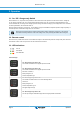
MultiPlus 2kVA 120V 3. Operation 3.1. On / Off / Charger-only Switch When switched to ‘on’, the product is fully functional. The inverter will come into operation and the LED ‘inverter on’ will light up. An AC voltage connected to the ‘AC in’ terminal will be switched through to the ‘AC out’ terminal, if within specifications. The inverter will switch off, the ‘Charger’ LED will light up and the charger commences charging.
MultiPlus 2kVA 120V On / Off / Charger-only switch = On. PowerControl and PowerAssist: The AC input is switched through and the charge current is zero. The inverter is switched on and, in case of PowerAssist, assists the AC input by supplying additional power to the load (see section 2.1). On / Off / Charger-only switch = On. Energy Storage System (ESS): The AC input voltage is switched through. The inverter is switched on and supplies power to the load, or excess power to the mains.
MultiPlus 2kVA 120V 4. Installation This product should be installed by a qualified electrician. CAUTION – To reduce risk of injury, charge only VRLA or Li-Ion batteries. Other types of batteries may burst causing personal injury and damage! 4.1. Location The product must be installed in a dry and well-ventilated area, as close as possible to the batteries. There should be a clear space of at least 10cm around the appliance for cooling. 1.
MultiPlus 2kVA 120V 4.3. Connection of the AC cabling This is a Safety Class I product (supplied with a protective grounding terminal). Uninterruptible protective grounding must be provided at the AC input and/or output terminals and/or chassis grounding point located externally on the product. The MultiPlus is provided with a ground relay (relay H, see appendix B) that automatically connects the Neutral output to the chassis if no external AC supply is available.
MultiPlus 2kVA 120V 4.4.4. Programmable relay The MultiPlus is equipped with a multi-functional relay that by default is programmed as an alarm relay. The relay can be programmed for all kinds of other applications however, for example to start a generator (VEConfigure software needed). 4.4.5. Parallel Connection (see appendix C) The MultiPlus can be connected in parallel with several identical devices. To this end, a connection is established between the devices by means of standard RJ45 UTP cables.
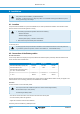
MultiPlus 2kVA 120V 5. Configuration Settings may only be changed by a qualified engineer. Carefully read the instructions before changes are made. Batteries should be placed in a dry and well-ventilated area during charging. 5.1. Standard settings: ready for use On delivery, the MultiPlus is set to standard factory values. In general, these settings are suitable for single-unit operation.
MultiPlus 2kVA 120V Input frequency range accepted by the MultiPlus. The MultiPlus synchronises within this range with the AC input frequency. The output frequency is then equal to the input frequency. Adjustability: 45 – 65Hz; 55 – 65Hz; 45 – 55Hz Input voltage range Voltage range accepted by the MultiPlus. The MultiPlus synchronises within this range with the AC input voltage. The output voltage is then equal to the input voltage.
MultiPlus 2kVA 120V suitable. If an extra high absorption voltage is selected for rapid charging (only possible for open, flooded batteries!), four hours is preferable. With DIP switches, a time of eight or four hours can be set. For the adaptive charge curve, this determines the maximum absorption time. Storage voltage, Repeated Absorption Time, Absorption Repeat Interval See Section 2. Bulk Protection Default setting: off. When this setting is ‘on’, the bulk charging time is limited to 10 hours.
MultiPlus 2kVA 120V A MK3-USB (VE.Bus to USB) interface. Alternatively, the Interface MK2.2b (VE.Bus to RS232) can be used (RJ45 UTP cable needed). 5.3.1. VE.Bus Quick Configure Setup VE.Bus Quick Configure Setup is a software program with which systems with a maximum of three MultiPlusses (parallel or three phase operation) can be configured in a simple manner. The software can be downloaded free of charge at www.victronenergy.com. 5.3.2. VE.
MultiPlus 2kVA 120V DS-1 Charge voltage off DS-1 off DS-2 DS-2 Charge voltage off DS-3 Charge voltage off on DS-2 off DS-1 on DS-2 on DS-3 on Example 1: (factory setting) Example 2 Example 3 1.2 GEL 14.4 V 1.2 Gel Victron Long Life 1.2 Tubular plate 15V 3 Search mode off Li-ion (LiFePO4) 3 Search mode off Search mode off 3 Store setting: off→ on→ off 3 Store setting: off→ on→ off 3 3 Store setting: off→ on→ off Store the settings by toggling DIP switch 3 one time.
MultiPlus 2kVA 120V 6. Maintenance The MultiPlus does not require specific maintenance. All maintenance should be performed by qualified personnel. Avoid moisture and oil/soot/vapours, and keep the device clean.
MultiPlus 2kVA 120V 7. Trouble Shooting Table Proceed as follows for quick detection of common faults. DC loads must be disconnected from the batteries and the AC loads must be disconnected from the inverter before the inverter and/or battery charger is tested. Consult your Victron Energy dealer if the fault cannot be resolved. Problem Cause Solution The inverter fails to operate when switched on The battery voltage is too high or too low Ensure that the battery voltage is within the correct value.
MultiPlus 2kVA 120V Problem Cause Alt 2: Battery temperature sensor faulty Solution Unplug battery temperature sensor from the MultiPlus. Reset the MultiPlus by switching it off, then wait for 4 seconds and switch it on again. If the MultiPlus now charges normally, the battery temperature sensor is faulty and needs to be replaced.
MultiPlus 2kVA 120V 8. Technical Data MultiPlus 12/2000/80 MultiPlus 24/2000/50 MultiPlus 48/2000/25 PowerControl / PowerAssist Yes Transfer switch 50A INVERTER Input voltage range 9,5 – 17V Output Output voltage: 120VAC ± 2% 19 – 33V Frequency: 60Hz ± 0,1% (1) Cont. output power at 25°C (3) 2000VA Cont. output power at 25°C 1600W Cont. output power at 40°C 1400W Cont.
MultiPlus 2kVA 120V MultiPlus 12/2000/80 MultiPlus 24/2000/50 MultiPlus 48/2000/25 1) Can be adjusted to 60Hz and to 240V 3) Non-linear load, crest factor 3:1 2) Protection 4) At 25°C ambient a. Output short circuit 5) Programmable relay which can be set for: b. Overload general alarm, DC under voltage or generator start/stop signal function c. Battery voltage too high AC rating: 230V/4A d. Battery voltage too low DC rating: 4A up to 35VDC, 1A up to 60VDC e. Temperature too high f.
MultiPlus 2kVA 120V 9. APPENDIX 9.1. Appendix A: overview connections EN A DIP switch Remove cover B On/off/charger only switch C VE.BUS Communications port D Temperature sensor E Alarm contact F Batterie Minus G Starter battery plus H Remote control I Mains IN J Mains/converter OUT K Battery plus L Earth connection 9.2.
MultiPlus 2kVA 120V EN D Input E Output F Ground in– and output connected to chassis G Backfeed safety relay H Ground relay (closed when backfeed is open) J Bidirectional converter K Chassis on input/output ground terminals should be permanently connected to ground 9.3.
MultiPlus 2kVA 120V 9.4. Appendix D: three-phase connection 9.5.
MultiPlus 2kVA 120V 4-stage charging: Bulk: Entered when charger is started. Constant current is applied until the gassing voltage is reached (14.4V resp. 28.8V, temperature compensated). Battery Safe: If, in order to quickly charge a battery, a high charge current in combination with a high absorption voltage has been chosen, the Multi will prevent damage due to excessive gassing by automatically limiting the rate of voltage increase once the gassing voltage has been reached.
Page 24 F E D C B A Rev01 1 147 76 506 1 236 2 2 3 3 138 147 4 7.5 4 4.1 30.7 415.3 6(4x) 5 5 134 201.00 189 49.7 6 55 32.5 67 67 7 98 6.2(3x) Dimensions in mm 7 8 8 Dimension Drawing - MultiPlus 2kVA PMP122200000 MultiPlus 12/2000/80-32 230V VE.Bus PMP122200100 MultiPlus 12/2000/80-50 120V VE.Bus PMP242200000 MultiPlus 24/2000/50-32 230V VE.Bus PMP242200100 MultiPlus 24/2000/50-50 120V VE.Bus PMP482200000 MultiPlus 48/2000/25-32 230V VE.