ENGLISH VictronConnect - VE.
VictronConnect - VE.Bus Configuration guide Table of Contents 1. Warning ................................................................................................................................ 1 2. Introduction ........................................................................................................................... 2 3. Limitations ............................................................................................................................. 3 3.1.
VictronConnect - VE.Bus Configuration guide 10.5. AC Input Control ......................................................................................................... 10.5.1. When can the grid be controlled? ............................................................................ 10.5.2. Conditional AC input activation ............................................................................... 10.5.3. Load Conditions ............................................................................
VictronConnect - VE.Bus Configuration guide 1. Warning The features described in this document are powerful tools. They are intended for use by Victron-trained Engineers, Installers and Dealers. Its usage must not be attempted by system Owners and Users. Configuring our Inverter/chargers, such as Multis and Quattros, requires both training and experience. Victron offers no direct support for un-trained individuals carrying-out configuration. Settings are protected by a password.
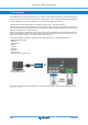
VictronConnect - VE.Bus Configuration guide 2. Introduction The VE.Bus features of VictronConnect App allows you to configure, monitor, update and diagnose your VE.Bus Victron product. VictronConnect connects to the inverters via a USB-MK3 accessory cable, or via the VE.Bus Smart Dongle (both sold separately). The specific MK3 VE.Bus component is available for Android, Windows, and macOS X (but not iOS). The specific VE.Bus Smart dongle component is available for Android, macOS X, iOS, (but not Windows).
VictronConnect - VE.Bus Configuration guide 3. Limitations 3.1. VictronConnect vs VEConfigure & VEFlash VictronConnect is replacing VEConfigure and VEFlash. Its easier to use and works on more devices, not only on Windows. The following features are not yet supported in VictronConnect. If you require this advanced functionality, you will still need to use VEConfigure.
VictronConnect - VE.Bus Configuration guide 4. Overview Video There is a video overview of this document, and it is intended to be used along side the more in-depth written documentation. https://player.vimeo.
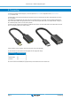
VictronConnect - VE.Bus Configuration guide 5. Connecting Connecting the VE.Bus Inverter/Charger to your device requires an MK3-USB for configuration mode, or VE.Bus Smart Dongle for status mode. The MK3-USB or Smart dongle goes between the VE.Bus port on the inverter/charger, and either USB or Bluetooth connection on your computer. You will also need a straight RJ45 UTP cable. Also known as Ethernet patch or LAN cables. Use an industrially manufactured cable. Handcrimped cables often give problems.
VictronConnect - VE.Bus Configuration guide 6. Demo Mode Menu You can learn more about VictronConnect using the demo menu option. This option allows you to load a “demo” device which simulates a real system. You can then adjust the settings/options. An in-app description in provded for some settings. There is a choice of demo devices: To access demo mode, select the three bar icon at the top left of the device list. Then Demo library. Scroll through the options and then click or tap your selection.
VictronConnect - VE.Bus Configuration guide 7. Display Options There are two different modes available when connecting to a VE.
VictronConnect - VE.Bus Configuration guide 8. Status Mode Status is available on Windows, macOS, Android and iOS operating systems. You can access Status by either the MK3-USB or via Bluetooth with the VE.Bus Smart Dongle. From the status window it is possible to switch the device On / Off / Charger Only from the switch button icon. It is also possible to quickly adjust the AC input current limit (if the overruled by the remote panel setting is enabled).
VictronConnect - VE.Bus Configuration guide 9. Settings Mode You can only access Settings with a MK3-USB. You cannot use a VE.Bus Smart Dongle to access Settings Mode. Settings is available on Windows, macOS and Android operating systems. Settings on iPhone is not supported at this time, as iPhone does not support OTG connections from USB and is unable to connect to the MK3-USB.
VictronConnect - VE.Bus Configuration guide 10. Description of Settings 10.1. General 10.1.1. System frequency setting Alters the output frequency setting for the inverter. 10.1.2. AC1 input current limit This setting is only active if no system panel is installed (is overruled by the remote panel if connected). 10.1.3. Current limit overruled by remote If Overruled by remote is enabled, the input current limit can be set remotely by a GX Device or a Digital Multi Control.
VictronConnect - VE.Bus Configuration guide 10.1.6. Battery capacity In order for the battery monitor to be able to correctly calculate the "state of charge" the battery capacity of the connected batteries must be known. Use this setting to specify the connected battery capacity in Ah. 10.1.7. State of charge when bulk finished Use this setting to specify what the "state of charge" is set to when the Bulk phase is finished.
VictronConnect - VE.Bus Configuration guide 10.2.4. Country / grid code standard Grid code setting is not yet available in VictronConnect. Depending on the installation and regional requirements you may need to need to use VEConfigure to adjust additional settings. 10.3. Inverter 10.3.1. Inverter output voltage This is normally 120/230 Vac. 10.3.2. Ground Relay Used to enable/disable the internal ground relay functionality. Connection between N and PE during inverter operation.
VictronConnect - VE.Bus Configuration guide 10.3.5. DC input low pre-alarm DC input low pre-alarm With this setting one can determine the level at which the Low batter pre-alarm indication starts. Note that in fact the parameter which is changed is an offset voltage relative to the DC input low restart level which in its turn is relative to the DC input low shut-down level.
VictronConnect - VE.Bus Configuration guide 10.4. Charger 10.4.1. Enable charger The inverter and assist functions of the Multi will continue to operate, but it will no longer charge; the charging current is therefore zero! 100% self-consumption by disabling the charge functionality of the Multi It can be quite expensive to charge the batteries from the grid. Lead-acid batteries have a low charge efficiency. About 20% of the energy used to charge the batteries is lost in the form of heat.
VictronConnect - VE.Bus Configuration guide 10.4.3. Float voltage Use this setting to specify the Float voltage. Float stage is reduced voltage from absorption, used to trickle in current to finish battery charge without creating excess heat or gassing. 10.4.4. Absorption voltage Use this setting to specify the Absorption voltage. Absorption is the charge phase where the battery is held at continuous target voltage with variable current. 10.4.5.
VictronConnect - VE.Bus Configuration guide Re-bulk voltage The Re-bulk voltage is the point that the charger returns to the bulk charging stage. It depends upon the float voltage. Lithium batteries tend to have a more stable voltage output and a narrower voltage range than lead acid batteries, so in lithium mode the value between float and re-bulking is reduced.
VictronConnect - VE.Bus Configuration guide • In this scenario the Multi will look at the battery voltage. It will let the grid in when the battery voltage is too low, for a certain amount of time. It will ignore the grid as soon as the battery voltage has increased above a certain level, for a certain amount of time. • The multi can also disconnect the grid on battery state of charge. The grid is ignored when the AC loads are low.
VictronConnect - VE.Bus Configuration guide Activate when load is higher than W Delay before activation T Deactive when load is lower than W Delay before deactivation T 10.5.4. Battery Conditions This setting can be used to charge the batteries from the grid should the batteries get too empty. This can occur, for example, at night or during a long period of bad weather. In this example, the grid is not ignored when the battery voltage is less than 47 Volt.
VictronConnect - VE.Bus Configuration guide 11. Firmware Updates 11.1. When to do a firmware update It is not required to keep your Victron equipment updated to the latest firmware version. Stable systems should be left with their current firmware. Here is when to perform a firmware update: • During commissioning / first install; • When trouble shooting; • To add a new feature that is required by the installation. Firmware updates are only available in Settings Mode, requiring a password - zzz 11.2.
VictronConnect - VE.
VictronConnect - VE.Bus Configuration guide If the firmware update fails, please attempt it again. If you still cannot recover the unit, Please use the alternative method and follow these steps using the VEFlash software instead. 11.4. Firmware updates with multiple units (eg 3 phase) It is possible to use VictronConnect to efficiently update the firmware for 3 phase, or parallel units. To do this, the units must already be programmed for their multiple unit configuration and connected to each other.
VictronConnect - VE.Bus Configuration guide 12. Parallel, Three, Split-phase systems Until now our VE.Bus Quick Configure software was required to set up a complex VE.Bus System. This is not the case anymore as VictronConnect can now be used to configure systems of up to three units. Watch this video where we demonstrate all steps involved in configuring a three phase system in just a few clicks. Please note a password is required for this feature, the password is available from your Victron supplier.
VictronConnect - VE.Bus Configuration guide 13. Troubleshooting 13.1. I am having bluetooth connection issues If you are having difficulty with connecting to a VE.Bus device with a laptop and an MK3-USB adaptor, try the following troubleshooting steps to help isolate the issue. 1. Make sure the device is connected to a power supply and switched on 2. Test the cable with a cable-tester and/or try another one. There can be a difference in pin arrangement in some network cables.