ENGLISH MultiPlus-II 12V 3kVA 2x120V Rev 02 06/2021
MultiPlus-II 12V 3kVA 2x120V Table of Contents 1. IMPORTANT SAFETY INSTRUCTIONS - Save these instructions! .......................................................... 1 2. Description ............................................................................................................................ 2 2.1. 120/240V input and output, or 120V input and output (always 120V output when in inverter mode) .............. 2 2.2. Other features ................................................................
MultiPlus-II 12V 3kVA 2x120V D. APPENDIX D: Three phase connection ........................................................................................ 30 E. APPENDIX E: Charge algorithm ................................................................................................. 31 F. APPENDIX F: Temperature compensation ..................................................................................... 32 G. APPENDIX G: Dimensions ................................................................
MultiPlus-II 12V 3kVA 2x120V 1. IMPORTANT SAFETY INSTRUCTIONS - Save these instructions! In general Please read the documentation supplied with this product first, so that you are familiar with the safety signs en directions before using the product. This product is designed and tested in accordance with international standards. The equipment should be used for the designated application only. Warning – These servicing instructions are for use by qualified personnel only.
MultiPlus-II 12V 3kVA 2x120V 2. Description 2.1. 120/240V input and output, or 120V input and output (always 120V output when in inverter mode) The AC input can be supplied from a split-phase 120/240V source or a single-phase 120V source. When an AC source is available, the MultiPlus will feed through the AC to its output. The output will therefore mirror the AC input. The inverter/charger connects to the neutral and the preferred input line (L1).
MultiPlus-II 12V 3kVA 2x120V The microprocessor-driven adaptive battery management system can be adjusted for various types of batteries. The adaptive function automatically adapts the charging process to battery use. The right amount of charge: variable absorption time In the event of slight battery discharge, absorption is kept short to prevent overcharging and excessive gas formation. After deep discharging, the absorption time is automatically extended in order to fully charge the battery.
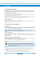
MultiPlus-II 12V 3kVA 2x120V 3. Operation 3.1. On/Off/Charger Only Switch When switched to ‘on’, the product is fully functional. The inverter will come into operation and the LED ‘inverter on’ will light up. An AC voltage connected to the ‘AC in’ terminal will be switched through to the ‘AC out’ terminal, if within specifications. The inverter will switch off, the ‘mains on’ LED will light up and the charger commences charging.
MultiPlus-II 12V 3kVA 2x120V c. Switch once more rapidly from ‘on’ to ‘charger only’ and leave the switch in this position. 4. On the MultiPlus-II (and, if connected, on the MultiControl panel) the three LEDs ‘Bulk’, ‘Absorption’ and ‘Float’ will now flash 5 times. 5. Subsequently, the LEDs ‘Bulk’, ‘Absorption’ and ‘Float’ will each light during 2 seconds. a. If the switch is set to ‘on’ while the ‘Bulk’ LED lights, the charger will switch to equalisation. b.
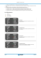
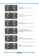
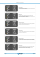
MultiPlus-II 12V 3kVA 2x120V Low battery alarm The inverter has switched off due to low battery voltage. The "low battery" LED is blinking. Temperature pre-alarm The internal temperature is reaching a critical level. The "temperature" LED is blinking. Temperature alarm The inverter has switched off due it's internal temperature being too high. The "temperature" LED is on. Overload pre-alarm and low battery pre-alarm The battery is nearly exhausted and the nominal output of the inverter is exceeded.
MultiPlus-II 12V 3kVA 2x120V Bulk charging The AC input voltage is switched through and the charger operates in bulk mode. The "bulk" LED is on. BatterySafe The mains voltage is switched through and the charger is on. However, the set absorption voltage has not yet been reached. The "bulk" and "absorption" LEDs are both on. Absorption charging The mains voltage is switched through and the charger operates in absorption mode. The "absorption" LED is on.
MultiPlus-II 12V 3kVA 2x120V PowerAssist The AC input is switched through, but the load requires more current than the preset maximum input current. The inverter is switched on to supply the required additional current. The "mains on" LED is on and the "inverter" LED is blinking. For more error codes see section 7.3 For the latest and most up to date information about the blink codes, please refer to the Victron Toolkit app.
MultiPlus-II 12V 3kVA 2x120V 4. Installation This product may only be installed by a qualified electrical engineer. 4.1. Location The product must be installed in a dry and well-ventilated area, as close as possible to the batteries. There should be a clear space of at least 10 cm around the appliance for cooling. Excessively high ambient temperature will result in the following: • Reduced service life. • Reduced charging current. • Reduced peak capacity, or shutdown of the inverter.
MultiPlus-II 12V 3kVA 2x120V WARNING – RISK OF EXPLOSIVE GASES) WORKING IN VICINITY OF A LEAD-ACID BATTERY IS DANGEROUS. BATTERIES GENERATE EXPLOSIVE GASES DURING NORMAL BATTERY OPERATION. FOR THIS REASON, IT IS OF UTMOST IMPORTANCE THAT EACH TIME BEFORE SERVICING THE UNIT IN THE VICINITY OF THEBATTERY, YOU READ THIS MANUAL AND FOLLOW THE INSTRUCTIONS EXACTLY.
MultiPlus-II 12V 3kVA 2x120V Recommended cable lugs Size AWG 2/1 Molex part no. 19221-0243 AWG 1/0 Molex part no. 19221-0240 * Follow local installation rules. ** Do not locate battery cables in a closed conduit *** “2x” means two positive and two negative cables. Remark: Internal resistance is the important factor when working with low capacity batteries. Please consult your supplier or the relevant sections of our book ‘Energy Unlimited’, downloadable from our website.
MultiPlus-II 12V 3kVA 2x120V Do not invert neutral and phase when connecting the AC. The shore or mains cable must be connected to the Multi with the aid of a three-wire 90ºC (194ºF) copper cable. AC-in AC-Out-1 AC-Out-2 Rated current 50 A 75 A 50 A Recommend fuse or circuit breaker 50 A 75 A 50 A Minimum wire gauge AWG 6 AWG 6 AWG 6 The inverter does incorporate a mains frequency isolating transformer. This precludes the possibility of DC current at any AC port.
MultiPlus-II 12V 3kVA 2x120V During battery charging, the MultiPlus-II will compensate the voltage drop over the DC cables up to a maximum of 1 Volt (i.e. 1V over the positive connection and 1V over the negative connection). If the voltage drop threatens to become larger than 1V, the charging current is limited in such a way that the voltage drop remains limited to 1V. 4.4.6.
MultiPlus-II 12V 3kVA 2x120V 5. Configuration This section is intended mainly for stand-alone applications. Settings may only be changed by a qualified electrical engineer. Read the instructions thoroughly before implementing changes. During setting of the charger, the AC input must be removed. 5.1. Standard settings: ready for use On delivery, the MultiPlus-II is set to standard factory values. In general, these settings are suitable for single-unit operation.
MultiPlus-II 12V 3kVA 2x120V Adjustability: 50 Hz; 60 Hz Input frequency range Input frequency range accepted by the MultiPlus-II. The MultiPlus-II synchronises within this range with the AC input frequency. The output frequency is then equal to the input frequency. Adjustability: 45 – 65 Hz; 45 – 55 Hz; 55 – 65 Hz Input voltage range Voltage range accepted by the MultiPlus-II. The MultiPlus-II synchronises within this range with the AC input. The output voltage is then equal to the input voltage.
MultiPlus-II 12V 3kVA 2x120V The standard setting is the most suitable for Victron Gel Deep Discharge, Gel Exide A200, and tubular plate stationary batteries (OPzS). This setting can also be used for many other batteries: e.g. Victron AGM Deep Discharge and other AGM batteries, and many types of flat-plate flooded batteries.
MultiPlus-II 12V 3kVA 2x120V When WeakAC is on, the maximum charge current is reduced by approximately 20%. BoostFactor Change this setting only after consulting with Victron Energy or with an engineer trained by Victron Energy! Programmable relay The relay can be programmed for all kinds of other applications, for example as a starter relay for a generator. Auxiliary AC output (AC-out-2) Intended for non-critical loads and directly connected to the AC input.
MultiPlus-II 12V 3kVA 2x120V 6. Maintenance The MultiPlus-II does not require specific maintenance. It will suffice to check all connections once a year. Avoid moisture and oil/ soot/vapours, and keep the device clean.
MultiPlus-II 12V 3kVA 2x120V 7. Error Indications With the procedures below, most errors can be quickly identified. If an error cannot be resolved, please refer to your Victron Energy supplier. We recommend to use the toolkit app to link LED alarm codes to a description of the problem/alarm, see https:// www.victronenergy.com/support-and-downloads/software#victron-toolkit-app 7.1. General error indications Problem Cause Solution No output voltage on ACout-2.
MultiPlus-II 12V 3kVA 2x120V Problem The charger does not operate. ‘Bulk’ LED flashes and ‘Mains on’ LED illuminates Cause MultiPlus-II is in ‘Bulk protection’ mode thus, the maximum bulk charging time of 10 hours is exceeded. Such a long charging time could indicate a system error (e.g. a battery cell short-circuit). The battery is not completely charged. The battery is overcharged. The charging current drops to 0 as soon as the absorption phase initiates. Solution Check your batteries.
MultiPlus-II 12V 3kVA 2x120V Absorption and float LEDs flash synchronously (simultaneously). The battery temperature as measured has an extremely unlikely value. The sensor is probably defective or has been incorrectly connected. The device will remain in normal operation. If the "inverter on" LED flashes in phase opposition, this a VE.Bus error code (see further on). 7.3. VE.Bus LED indications Equipment included in a VE.Bus system (a parallel or 3-phase arrangement) can provide so-called VE.
MultiPlus-II 12V 3kVA 2x120V All of the conditions below must be met!: 1. The device is in error! (No AC output) 2. Inverter LED flashes (in opposition to any flashing of the Bulk, Absorption or Float LED) 3.
MultiPlus-II 12V 3kVA 2x120V Bulk LED Absorption LED Float LED Page 23 Code Meaning: Cause/solution: 5 Overvoltage on AC-out. Check the AC cables. 10 System time synchronisation problem occurred. Should not occur in correctly installed equipment. Check the communication cables. 14 Device cannot transmit data. Check the communication cables (there may be a short circuit) 17 One of the devices has assumed ‘master’ status because the original master failed. Check the failing unit.
MultiPlus-II 12V 3kVA 2x120V 8. Technical Specifications MultiPlus-II 12V 3kVA 2x120V PowerControl & PowerAssist Yes (on L1 input) Transfer switch 50 A Maximum AC input current 50 A (each leg) INVERTER DC Input voltage range 9,5 – 17 V Output when in inverter mode Output voltage: 120 VAC ± 2% Frequency: 60 Hz ± 0,1% (1) Cont. output power at 25°C (3) 3000 VA Cont. output power at 25°C 2400 W Cont. output power at 40°C 2200 W Cont.
MultiPlus-II 12V 3kVA 2x120V MultiPlus-II 12V 3kVA 2x120V 120/240 V AC-connection Screw terminals 21 mm² (4 AWG) Weight 22 kg (48 lb) Dimensions (hxwxd) mm 578 x 275 x 148 (23 x 11 x 6 inch) STANDARDS Safety Emission, Immunity EN-IEC 60335-1, EN-IEC 60335-2-29 EN 55014-1, EN 55014-2 EN-IEC 61000-3-2, EN-IEC 61000-3-3 IEC 61000-6-1, IEC 61000-6-2, IEC 61000-6-3 1. Can be adjusted to 50 Hz 2. Protection key: a. output short circuit b. overload c. battery voltage too high d. battery voltage too low e.
MultiPlus-II 12V 3kVA 2x120V Appendix A.
MultiPlus-II 12V 3kVA 2x120V D Auxiliary relay - From left to right: NO, NC, COM E Primary ground connection (PE) - M8 bolt F Trickle charge positive terminal (12 and 24V model only) G Battery positive connections - 2 x M8 bolt H Battery minus connections - 2 x M8 bolt I Power switch - To switch: 1=On, 0=Off, ||=charger only J Push button A - To perform a startup without assistants K Remote on/off connector - Short contact to switch to “on” L VE.
MultiPlus-II 12V 3kVA 2x120V Appendix B. APPENDIX B: Block diagram L2 L1 ACout2 N PE L2 L2 L1 L1 ACout1 AC in N N PE PE ~ = + - Battery PE * See table in Chapter 4.
MultiPlus-II 12V 3kVA 2x120V Appendix C.
MultiPlus-II 12V 3kVA 2x120V Appendix D.
MultiPlus-II 12V 3kVA 2x120V Appendix E. APPENDIX E: Charge algorithm 4-stage charging: Bulk Entered when charger is started. Constant current is applied until nominal battery voltage is reached, depending on temperature and input voltage, after which constant power is applied up to the point where excessive gassing is starting (14.4 V resp. 28.8 V, temperature compensated). Battery Safe The applied voltage to the battery is raised gradually until the set Absorption voltage is reached.
MultiPlus-II 12V 3kVA 2x120V Appendix F. APPENDIX F: Temperature compensation EN Default output voltages for Float and Absorption are at 25 °C. Reduced Float voltage follows Float voltage and Raised Absorption voltage follows Absorption voltage. In adjust mode temperature compensation does not apply.
MultiPlus-II 12V 3kVA 2x120V Appendix G. APPENDIX G: Dimensions 1 2 4 3 6 5 7 8 Dimension Drawing - MultiPlus-II PMP122305100 MultiPlus-II 12/3000/120-50 2x120V A A 275.4 148.2 7.5 6(4x) 6.2(3x) 32.5 57.5 98.3 55 B B 87.5 577.6 87.5 478 C C 125.6 44.9 5.1 137.6 D 175 242 D 148.
MultiPlus-II 12V 3kVA 2x120V Appendix H.
MultiPlus-II 12V 3kVA 2x120V L2 } L1 0 VAC N 120 VAC 120 VAC PE L2 L2 0 VAC L1 L1 N N PE PE Transfer relays } 120 VAC 120 VAC AC 0ut 1 AC in } AC 0ut 2 Output relay internal ground relay Battery Power flow single phase Page 35 APPENDIX H: Power flow diagrams
MultiPlus-II 12V 3kVA 2x120V L2 L1 N } 240 VAC 120 VAC 120 VAC PE L2 L2 } L1 L1 240 VAC 120 VAC N N 120 VAC PE PE Transfer relays AC 0ut 1 AC in } AC 0ut 2 Output relay internal ground relay Battery Power flow split phase Page 36 APPENDIX H: Power flow diagrams