
MultiPlus-II 24/3000/70-50 2x120V Manual

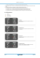
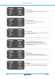
Table Of Contents
- MultiPlus-II 12V 3kVA 2x120V
- Table of Contents
- 1. IMPORTANT SAFETY INSTRUCTIONS - Save these instructions!
- 2. Description
- 3. Operation
- 4. Installation
- 4.1. Location
- 4.2. Connection of battery cables
- 4.3. Connection of the AC cabling
- 4.4. Optional Connections
- 4.4.1. Remote Control
- 4.4.2. Programmable relay
- 4.4.3. Programmable analog/digital input/output ports
- 4.4.4. Starter battery (connection terminal E, see appendix A)
- 4.4.5. Voltage sense (connection terminal J, see appendix A)
- 4.4.6. Temperature sensor (connection terminal J, see appendix A)
- 4.4.7. Parallel Connection
- 4.4.8. Three-phase operation
- 5. Configuration
- 6. Maintenance
- 7. Error Indications
- 8. Technical Specifications
- Appendix A. APPENDIX A: Connection overview
- Appendix B. APPENDIX B: Block diagram
- Appendix C. APPENDIX C: Parallel connection
- Appendix D. APPENDIX D: Three phase connection
- Appendix E. APPENDIX E: Charge algorithm
- Appendix F. APPENDIX F: Temperature compensation
- Appendix G. APPENDIX G: Dimensions
- Appendix H. APPENDIX H: Power flow diagrams

2. Description
2.1. 120/240V input and output, or 120V input and output (always 120V output
when in inverter mode)
The AC input can be supplied from a split-phase 120/240V source or a single-phase 120V source.
When an AC source is available, the MultiPlus will feed through the AC to its output. The output will therefore mirror the AC input.
The inverter/charger connects to the neutral and the preferred input line (L1). The power needed to charge the batteries will
therefore be drawn from L1 (see fig )
The MultiPlus switches to inverter operation when no AC source is available. The inverter output is 120V single phase. In invert
mode, the MultiPlus connects both output lines (L1 and L2) together to provide 120VAC to loads on either line.
Any 240V loads will therefore be supplied only when the MultiPlus is supplied by a split-phase AC source. This prevents heavy
loads such as water heaters or 240V air conditioners from discharging the battery.
240V loads should be connected between L1 and L2 which could be either ACout1 or ACout2. There will be 240V between them
when the unit is connected to a split-phase input and 0V otherwise (single phase grid or inverter mode). The voltage L1-N and L2-
N will be 120V regardless of single or split-phase input. This can be better understood with the addition of the power flow
diagrams.
2.2. Other features
Automatic and uninterruptible switching (AC out 1)
In the event of a supply failure or when the generating set is switched off, the MultiPlus-II will switch over to inverter operation and
take over the supply of the connected devices. The transfer time of the L1 output is less than 18 milliseconds so that computers
and other electronic equipment will continue to operate without disruption.
The transfer time of the L2 output is longer: approximately 40 milliseconds.
Auxiliary output (AC out 2)
The second (auxiliary) output is live only when AC is available on the input of the MultiPlus. Loads that should not discharge the
battery can be connected to this output. Please enter “AC-out-2” in the search box on our website and find the latest information
about other applications.
Three-phase capability
Three units can be configured for three-phase output. Up to 6 sets of three units can be parallel connected. In multi-phase setups,
L2 the output is disabled for all units.
PowerControl – maximum use of limited AC power
A maximum grid or generator current can be set. The MultiPlus will then take account of other AC loads and use whatever is extra
for battery charging, thus preventing the generator or grid from being overloaded (PowerControl function).
PowerAssist – Extended use of a generator or shore current: the MultiPlus-II “co-supply” feature
PowerAssist takes the principle of PowerControl to a further dimension. Where peak power is so often required only for a limited
period, the MultiPlus-II will compensate insufficient generator, shore or grid power with power from the battery. When the load
reduces, the spare power is used to recharge the battery (available on L1 input only).
Programmable relay
The MultiPlus is equipped with a programmable relay. The relay can be programmed for different applications, for example as a
starter relay for a generator.
External current transformer (optional)
External current transformer option to implement PowerControl and PowerAssist with external current sensing.
Programmable analog/digital input/output ports (Aux in 1 and Aux in 2, see appendix)
The MultiPlus is equipped with 2 analog/digital input/output ports. These ports can be used for several purposes. One application
is communication with the BMS of a lithium-ion battery.
2.3. Battery charger
2.3.1. Lead-acid batteries
Adaptive 4-stage charge algorithm: bulk – absorption – float – storage
MultiPlus-II 12V 3kVA 2x120V
Page 2 Description