
MultiPlus-II 24/3000/70-50 2x120V Manual

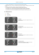
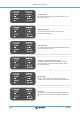
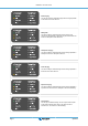
Table Of Contents
- MultiPlus-II 12V 3kVA 2x120V
- Table of Contents
- 1. IMPORTANT SAFETY INSTRUCTIONS - Save these instructions!
- 2. Description
- 3. Operation
- 4. Installation
- 4.1. Location
- 4.2. Connection of battery cables
- 4.3. Connection of the AC cabling
- 4.4. Optional Connections
- 4.4.1. Remote Control
- 4.4.2. Programmable relay
- 4.4.3. Programmable analog/digital input/output ports
- 4.4.4. Starter battery (connection terminal E, see appendix A)
- 4.4.5. Voltage sense (connection terminal J, see appendix A)
- 4.4.6. Temperature sensor (connection terminal J, see appendix A)
- 4.4.7. Parallel Connection
- 4.4.8. Three-phase operation
- 5. Configuration
- 6. Maintenance
- 7. Error Indications
- 8. Technical Specifications
- Appendix A. APPENDIX A: Connection overview
- Appendix B. APPENDIX B: Block diagram
- Appendix C. APPENDIX C: Parallel connection
- Appendix D. APPENDIX D: Three phase connection
- Appendix E. APPENDIX E: Charge algorithm
- Appendix F. APPENDIX F: Temperature compensation
- Appendix G. APPENDIX G: Dimensions
- Appendix H. APPENDIX H: Power flow diagrams

Low battery alarm
The inverter has switched off due to low battery voltage. The "low
battery" LED is blinking.
Temperature pre-alarm
The internal temperature is reaching a critical level. The
"temperature" LED is blinking.
Temperature alarm
The inverter has switched off due it's internal temperature being too
high. The "temperature" LED is on.
Overload pre-alarm and low battery pre-alarm
The battery is nearly exhausted and the nominal output of the
inverter is exceeded. The "overload" and "low battery" LEDs are
both blinking alternately,
Ripple pre-alarm
The ripple voltage on the battery terminals is too high. The
"overload" and "low battery" LEDs are both blinking simultaneously.
Ripple alarm
The inverter has switched off due to excess ripple voltage on the
battery terminals. The "overload" and "low battery" LEDs are both
on.
MultiPlus-II 12V 3kVA 2x120V
Page 6 Operation