
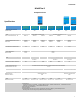
MultiPlus-II to MultiGrid and MultiPlus comparison


5
MultiGrid
A
AC input: Left to right: L (phase), N (neutral), PE (earth/ground).
B
2x RJ45 connector for remote control and/or parallel / three-phase operation (VE.Bus)
C
Load connection. AC out1. Left to right: L (phase), N (neutral), PE (earth/ground).
D
Load connection. AC out2.
Left to right: PE (earth/ground), L (phase), N (neutral).
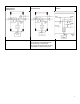
E
Terminals
Temperature sensor (not available on the MultiPlus-II: VE.Bus Smart dongle needed)
Aux input 1 (same fio as MultiPlus-II)
Aux input 2 (same fio as MultiPlus-II)
Starter battery plus + (starter battery minus must be connected to service battery minus) Not available on the
MultiPlus-II.
Programmable relay contacts K1
Programmable relay contacts K2
Voltage sense (not available on the MultiPlus-II: VE.Bus Smart dongle needed)
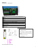
F
Double M8 battery minus connection.
G
Double M8 battery positive connection.
H
Connector for remote switch:
Short left and middle terminal to switch ‘on’.
Short right and middle terminal to switch to ‘charger only’.(not available on MultiPlus-II).
I
Alarm contact: (left to right) NC, NO, COM.
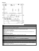
K
Pushbuttons for set-up mode. Not available on MultiPlus-II.
L
Primary ground connection M8 (PE).
M
Dipswitches DS1- DS8 for set-up mode. Not available on MultiPlus-II.
N
Slide switches, factory setting: SW1= down (off) position, SW2 = down (off) position. Not available on MultiPlus-II.
SW1: down (off) = internal GND relay selected, up (on) = external GND relay selected (to connect ext GND relay:
see E). Not available on MultiPlus-II
SW2: No application. To be used for future features. Not available on MultiPlus-II