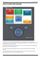
2019-08-15 12:22 1/39 Color Control GX manual Color Control GX manual The Color Control GX (CCGX) sits at the heart of your energy installation. All the other systemcomponents - such as inverter/chargers, solar chargers, and batteries - are connected to it. The CCGX ensures that they all work in harmony.
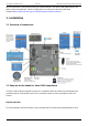
Last update: 2019-08-15 11:42 ccgx:start https://www.victronenergy.com/live/ccgx:start All the information in this manual refers to the latest software. Your device will update itself to the latest version automatically. Check our blog posts to see that your device has the latest firmware:https://www.victronenergy.com/blog/category/firmware-software/ 1. Installation 1.1 Overview of connections 1.
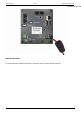
2019-08-15 12:22 3/39 Color Control GX manual around the power lea HQ1654 and earlier For serial numbers HQ1654 and earlier, mount the snap-on ferrite beads as below: Victron Energy - https://www.victronenergy.
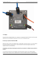
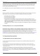
Last update: 2019-08-15 11:42 ccgx:start https://www.victronenergy.com/live/ccgx:start 1.3 Power Power the device using the Power in V+ connector. It accepts 8 to 70 V DC. The device will not power itself from any of the network connections. Be sure to use a 1A slow blow fuse. Powering in systems with VE.Bus BMS When the CCGX is used in an installation with a VE.Bus BMS, connect the Power in V+ on the CCGX to the terminal labelled 'Load disconnect' on the VE.Bus BMS.
2019-08-15 12:22 5/39 Color Control GX manual for any reason (after any operational fault or during a black start). The VE.Bus devices will not boot-up until the CCGX has power …but the CCGX will not boot-up until it has power. This deadlock can be rectified by briefly unplugging the CCGX VE.Bus cable at which point you will observe the VE.Bus products will immediately begin to boot-up. Or a modification can be done to the RJ45 cabling. See FAQ Q21 for more information about this.
Last update: 2019-08-15 11:42 ccgx:start https://www.victronenergy.com/live/ccgx:start Single VE.Bus products To connect a single VE.Bus product, connect it to one of the VE.Bus sockets on the back of the CCGX. Both sockets are identical, use either one. Use a standard RJ45 UTP cable, see our pricelist. Parallel, split- and three-phase VE.Bus systems To connect multiple VE.Bus products, configured as a parallel, split-phase or three phase VE.Bus system, connect either the first or the last VE.
2019-08-15 12:22 7/39 Color Control GX manual Alternatively the VE.Bus to VE.Can interface (ASS030520105) can be used. Add one for each additional system. Note that we advise against it; this interface is a deprecated product. Make sure that the VE.Can network is terminated and powered. For powering the VE.Can network, see Q17 in our data communication whitepaper. 1.4.2 Battery Monitor BMV-700 series; and MPPTs with a VE.
Last update: 2019-08-15 11:42 ccgx:start https://www.victronenergy.com/live/ccgx:start Other notes: 1. 2. 3. 4. In order to work with the CCGX an MPPT 150/70 needs run firmware v2.00 or newer. You can combine a Skylla-i control panel with a CCGX. You can combine a Ion Control panel with a CCGX. The Skylla-i, Lynx Shunt VE.Can, Lynx Ion + Shunt and the MPPTs with a VE.Can port all power the VE.Can network …so it won't be necessary to power the VE.Can network separately in these circumstances.
2019-08-15 12:22 9/39 Color Control GX manual For some tank senders it is also possible to configure the capacity and the fluid type from the CCGX for example the Maretron TLA100. This facility may be available with other senders made by other manufacturers - it's well-worth trying. To connect an NMEA2000 network to the VE.Can port on the CCGX, use a VE.Can to NMEA2000 cable. Alternatively, instead of a VE.Can to NMEA200, you can use a 3802 cable from Oceanic Systems: https://osukl.com/ve-can-adaptor/.
Last update: 2019-08-15 11:42 ccgx:start https://www.victronenergy.com/live/ccgx:start To monitor this data from your smartphone or tablet download the iOS or Android VRM App. In addition to remote monitoring, an active internet connection allows the CCGX to regularly check for a new firmware versions - which will be automatically downloaded and installed.
2019-08-15 12:22 11/39 Color Control GX manual 1.6.2 Wi-Fi USB dongle Using a Wi-Fi dongle it is possible to connect to WEP, WPA and WPA2 secured networks. There are four supported USB Wi-Fi dongles. Two of them are also available from stock at Victron Energy: Partno. BPP900100200 - CCGX WiFi module simple (Nano USB), small, low cost. Partno. BPP900200300 - Asus USB-N14, slightly higher cost and also better reception than the Nano USB. Supported since software version 2.23.
Last update: 2019-08-15 11:42 ccgx:start https://www.victronenergy.com/live/ccgx:start …but not on: iPhone 5s with iOS 8.1.1 1.6.5 IP Configuration Almost no installations will need the IP address configuration to be inserted manually as most systems support automatic IP configuration (DHCP) - and that is also the CCGX default setting.
2019-08-15 12:22 13/39 Color Control GX manual some mobile companies will report the data used via a website. The amount of data used is also very dependent on the system: More products connected to the CCGX will generate more data. A state change (from inverter to charger for example) will trigger a data transmission, so a system with very frequent state changes will also tend to generate more data. This is especially true in certain Hub-1 and Hub-2 systems. Note that CCGX versions prior to v1.
Last update: 2019-08-15 11:42 ccgx:start https://www.victronenergy.com/live/ccgx:start 1.8 Connecting a Fischer Panda Generator See CCGX & Fischer Panda generators. 2 Configuration 2.1 Configurable parameters After completing the installation and setting up the internet connection (if required), go through the menu from top to bottom to configure the CCGX: Item General Remote support Default Description Off Enable this to allow Victron engineers to access your system in case there is a problem.
2019-08-15 12:22 Item Default 15/39 Color Control GX manual Description Enable this for boats, vehicles and installations with DC loads and chargers - in addition to Multi and MPPT chargers. This won't be applicable to most off-grid installations; and any discrepancy between the DC current measured by the Multi, and by the BMV, will be attributed to a 'DC system'. This may be power-in from an alternator, or power-out from a pump, for example. Has DC system No A positive value indicates consumption.
Last update: 2019-08-15 11:42 ccgx:start https://www.victronenergy.com/live/ccgx:start Click the thumbnail below to see the complete menu-tree: 2.4 Battery State of Charge (SOC) https://www.victronenergy.
2019-08-15 12:22 17/39 Color Control GX manual 2.4.1 Which device should I use for SOC calculation? There are three products types that calculate State Of Charge (SOC). The CCGX itself does not calculate SOC, it only retrieves it from the connected devices. The three products that calculate SOC are: 1. Battery Monitors, such as the BMVs, the Lynx Shunt, or the Lynx Ion BMS 2. Multi and Quattro inverter/chargers 3. Batteries with built-in battery monitor and a (mostly CAN bus) connection to the CCGX.
Last update: 2019-08-15 11:42 ccgx:start https://www.victronenergy.com/live/ccgx:start Multi or Quattro. 3. In the same menu, verify that the option 'Use solar charger current to improve VE.Bus SOC' is enabled. Note that this is not a setting - it just an indicator of an automatic process. Note that this feature requires recent firmware versions in both the Multis or Quattros (402 minimum), and the CCGX (v2.06 minimum).
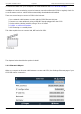
2019-08-15 12:22 19/39 Color Control GX manual VRM Portal FAQ - difference between BMV SOC and VE.Bus SOC CCGX Manual - configurable parameters. See Battery Monitor selection and Has DC System. 2.4.4 Selecting SOC source (Settings → System Setup → Battery monitor) In the image below you can see a range of selectable choices for the SOC values which are shown in the main Overview screen. Choose the source you want to see on the main Overview screen of your CCGX.
Last update: 2019-08-15 11:42 ccgx:start https://www.victronenergy.com/live/ccgx:start select one manually. 3. when there is no dedicated Battery Monitor, it will use the VE.Bus SOC. When should I use the 'No battery monitor' option?: Use that in systems where: 1. there is a Multi or Quattro installed 2. no BMV or other battery monitor is installed 3. the system has other DC loads, or other chargers, connected to the same battery, which are not connected to the CCGX. A short explanation: the VE.
2019-08-15 12:22 21/39 Color Control GX manual The limit as set by the user in the CCGX will be applied to all inputs where 'Overruled by remote', configured with VEConfigure, is enabled: Using the example of a boat with two AC inputs and a Quattro where: 1. A Genset capable of delivering 50A is connected to input 1; 2. Shore power is connected to input 2. (Available power depends on the rating of the harbour power-supply.) Configure the system exactly as in above VEConfigure screenshot.
Last update: 2019-08-15 11:42 ccgx:start https://www.victronenergy.com/live/ccgx:start Systems where it is not possible to control the input current limit It is not possible to control the input current limit in certain installations. In these cases, the CCGX menu will not allow changing the setting: 1. Installations with a VE.Bus BMS 2. Installations with a Digital Multi Control (or its predecessors) Also the on/off/charger only switch in the CCGX will be disabled in the case. In installation with a VE.
2019-08-15 12:22 23/39 Color Control GX manual Note that is still possible to set the input current limit to 0. When set to 0, the system will be in passthrough (charger disabled). Parallel and three phase systems The configured AC input current limit is the total limit per phase. 3.2 Phase rotation warning The AC supply, either Generator or Grid, to a three phase inverter/charger system needs to be in the correct rotation, also known as sequence.
Last update: 2019-08-15 11:42 ccgx:start https://www.victronenergy.com/live/ccgx:start And on the VRM Portal, it is visible on the VE.Bus Alarms & warnings widget on the Advanced page: And also it will be listed in the Alarm Log on VRM, and an email will be sent; using the VRM Alarm Monitoring system. 4 DVCC - Distributed Voltage and Current Control 4.1 Introduction and features Enabling DVCC changes a GX device from a passive monitor into an active controller.
2019-08-15 12:22 25/39 Color Control GX manual For systems with lead batteries, DVCC offers features such as a configurable system wide charge current limit and shared temperature sense. As also in above example, the available features and effects of enabling DVCC depend on the type of battery used. The effect also depends on the installed Victron components and their configuration. For the details, carefully study below chapters to fully understand DVCC for a particular system.
Last update: 2019-08-15 11:42 ccgx:start https://www.victronenergy.com/live/ccgx:start Lynx Ion + Shunt: v2.04 Lynx BMS: v1.09 In case of an ESS System, the ESS Assistant needs to be version 164 or later (Released in November 2017). 4.3 DVCC effects on the charge algorithm Our inverter/chargers and MPPT Solar Chargers use their own internal charge algorithm when in stand-alone mode.
2019-08-15 12:22 27/39 Color Control GX manual Internal The internal charge algorithm (bulk → absorption → float → re-bulk), and the configured charge voltages are active. Inverter/charger indicated charge state: bulk, absorption, float, and-so-forth. MPPT indicated charge state: bulk, absorption, float and-so-forth. (firmware version v1.42 onwards. Earlier versions have a bug that make the MPPT say “Ext. Control” when it is only being current limited; its internal charge algorithm still active.
Last update: 2019-08-15 11:42 ccgx:start https://www.victronenergy.com/live/ccgx:start This setting is available in the “Settings → “System Setup” menu on the GX device. Particulars: 1) In case a CANBUS-BMS is connected and the BMS requests a maximum charge current that is different from the user-configurable setting, the lower of the two will be used. 2) this mechanism only works for Victron inverter/chargers and Solar chargers.
2019-08-15 12:22 29/39 Color Control GX manual Shared Temperature Sense (STS) tbd 4.5 DVCC Features when using CAN-bus BMS Battery This chapter applies to all systems where an intelligent battery BMS is installed, and connected via CAN-bus. Note that this does not include the Victron VE.Bus BMS. Such intelligent BMS sends four parameters to the GX device: 1. Charge voltage limit (CVL): the maximum charge voltage that the battery currently accepts. 2.
Last update: 2019-08-15 11:42 ccgx:start https://www.victronenergy.com/live/ccgx:start A fixed solar offset of 0.4V is used instead of a variable 2V. (values for 48V systems, divide by 4 for 12V). Note that this solar offset is only applied when ESS-mode is set to Optimized in combination with the Feed-in excess solar charger power-setting enabled, or when ESS-mode is set to Keep batteries charged. Add Auto-recharge feature for the ESS Modes Optimized and Optimized (with BatteryLife).
2019-08-15 12:22 31/39 Color Control GX manual The transmission of the data logs has been designed to work also on bad internet connections. Lines of up to 70% permenant packet loss are still sufficient to get the data out, even if delayed in some cases. Adding an external storage device When unable to transmit the logs, then the GX device will store them to non-volatile storage (ie. data is not lost on a power loss or reboot). The GX device can store 48 hours worth of logs internally.
Last update: 2019-08-15 11:42 ccgx:start https://www.victronenergy.com/live/ccgx:start SDXC type microSD cards which have greater than 32 GB capacity are often formatted with exFAT, and therefore cannot be used with the CCGX without reformatting and possibly repartitioning. Manually transferring datalogs to VRM For devices permanently without Internet, it is possible to take the data out, and then upload it manually from a laptop. 1. go to Settings → VRM Portal, and click Eject the storage.
2019-08-15 12:22 33/39 Color Control GX manual 5.4 Trouble shooting data logging This chapter explains what to do when the GX Device cannot transmit data to the VRM Portal. The communication required to send logs to the VRM Portal is: 1. 2. 3. 4. Working DNS Proper IP address Working internet connection Outbound http(s) connection to http://ccgxlogging.victronenergy.com on port 80 and 443. Note that should never be an issue, unless on very specialized company networks.
Last update: 2019-08-15 11:42 ccgx:start https://www.victronenergy.com/live/ccgx:start in, should be lit or blinking. Two dead lights indicate a connection problem. WiFi When using Wi-Fi and the menu shows 'No Wi-Fi adapter connected' check the USB connection to the Wi-Fi dongle. Try to remove the dongle and insert it again. When using Wi-Fi and the State shows 'Failure', it might be that the Wi-Fi password is incorrect. Press 'Forget network' and try to connect again with the correct password. Step 3.
2019-08-15 12:22 35/39 Color Control GX manual restrictive firewall. Error #153 Connection error: this could indicate a routing problem. For details, check the shown error message: Error #154 DNS Failure: Make sure that a valid DNS server is configured in the Ethernet or WiFi menu. Typically this is assigned automatically by a DHCP server in a network. Error #155 Routing error: VRM is unreachable. This error occurs if an ICMP error is received indicating that no route exists to the VRM server.
Last update: 2019-08-15 11:42 ccgx:start https://www.victronenergy.com/live/ccgx:start 5.5 Analysing data offline, without VRM In certain cases, for example for very remote sites where there is no internet available, it can be useful to be able to analyse the data without first having to upload it to the VRM Portal. 1. Install VictronConnect on a Windows or Apple laptop 2. Insert the storage device containing the log file(s) 3.
2019-08-15 12:22 37/39 Color Control GX manual Trouble shooting tips: 1. 2. 3. 4. Make sure that basic communication with VRM works, see chapter 5.4. After enabling the feature, make sure to set (or disable) the password. Also make sure to restart the CCGX. Make sure to update the CCGX to the latest firmware version. The last stability improvement for Remote Console was made in version v2.30. 5. After the restart, check the Remote Console on VRM status shows online or a port number.
Last update: 2019-08-15 11:42 ccgx:start https://www.victronenergy.com/live/ccgx:start status into a large screen or screens at the helm of the vessel, so doing away with multiple gauges, brackets and wiring complications. A Victron system can be easily integrated into that, as shown in this video: https://www.youtube.com/watch?v=RWdEQfYZKEs Functionalities: Monitor shore power and generator status. Monitor battery status for one or more batteries.
2019-08-15 12:22 39/39 CCGX Manually updating firmware CCGX Remote VEConfigure and remote firmware updates CCGX Datasheet CCGX & Fischer Panda generators VRM Portal VRM Portal - trouble shooting Remote Console Venus OS - Beta testing Open source DISQUS View the discussion thread. From: https://www.victronenergy.com/live/ - Victron Energy Permanent link: https://www.victronenergy.com/live/ccgx:start Last update: 2019-08-15 11:42 Victron Energy - https://www.victronenergy.