
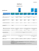
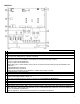
MultiPlus-II to MultiGrid and MultiPlus comparison

4
MultiPlus-II
PMP482305000 PMP482505000
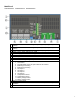
A
Load connection. AC out1. Left to right: N (neutral), PE (earth/ground), L
(phase)
B
AC input: Left to right: N (neutral), PE (earth/ground), L (phase)
C
Load connection. AC out2. Left to right: N (neutral), PE (earth/ground), L
(phase)
D
M8 battery positive connection.
E
M8 battery minus connection.
F
External current sensor (not available on MultiGrid)
G
RJ12 additional IO connector (see below)
H
2x RJ45 VE-BUS connector for remote control and/or parallel / three-phase
operation (VE.Bus)
I
Connector for remote switch: Short to switch “on”.
J
Programmable relay (left to right) NO, NC, COM.(virtual switch in
VE.Configure)
K
Primary ground connection M8 (PE).
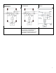
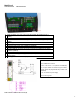
Detail of the RJ12 additional IO connector (G)
Detail of the RJ12 additional IO connector (G)
RJ12 additional IO connector
Aux in 1 and Aux in 2: 0 – 5V (same fio as in MultiGrid)
K1, K2: open collector 70V 100mA max (open collector
inputs, replaces the programmable relay contacts of the
MultiGrid)
12V: 12V 100mA max power supply
Gnd: common ground