
SmartSolar MPPT Manual
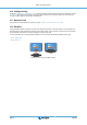
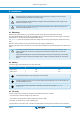
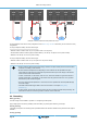
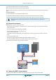
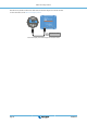
Table Of Contents
- MPPT solar charger manual
- Table of Contents
- 1. Safety precautions
- 2. Introduction
- 3. Features
- 4. Installation
- 5. Configuration and settings
- 6. Operation
- 7. Monitoring
- 8. Warranty
- 9. Troubleshooting and Support
- 9.1. The controller is not operational
- 9.2. Batteries are not charged
- 9.3. Batteries are undercharged
- 9.3.1. Too much DC load
- 9.3.2. Battery charge voltages are too low
- 9.3.3. The battery is almost full
- 9.3.4. Battery cable voltage drop
- 9.3.5. Temperature difference between solar charger and battery
- 9.3.6. Insufficient solar
- 9.3.7. Wrong temperature compensation setting
- 9.3.8. Battery charge current too low
- 9.4. Batteries are overcharged
- 9.5. Solar issues
- 9.5.1. PV reverse current too high
- 9.5.2. PV yield less than expected
- 9.5.3. Full rated output not reached
- 9.5.4. Max PV output power relates to battery voltage
- 9.5.5. Mixed PV panel types
- 9.5.6. PV connections burned or melted
- 9.5.7. MC4 connectors wrongly connected
- 9.5.8. Optimisers cannot be used
- 9.5.9. Earth fault detection missing
- 9.5.10. Ground current
- 9.6. Communication issues
- 9.7. Settings or firmware issues
- 9.8. Operation issues
- 10. Technical specifications
- 11. Appendix

The positive and negative of the PV array should not be grounded.
Ground the frame of the PV panels to reduce the impact of lightning.
Do not connect the solar charger to a grounded PV array. Only one ground connection is allowed, and this should be near the
battery.
Ground fault detection
The solar charger does not have internal ground fault protection.
The USA National Electrical Code (NEC) requires the use of an external ground fault protection device (GFPD).
The system electrical negative should be bonded through a GFPD to earth ground at one (and only one) location.
When a ground fault is indicated, battery terminals and connected circuits may be un-grounded and
hazardous.
4.5. Electrical connections
Make all electrical connections in the following order:
• Confirm correct battery polarity, then connect the battery (this will allow the solar charger to recognize the system voltage).
Torque moment 1.6Nm.
• Connect the VE.Direct communication cable (if applicable).
• Confirm correct PV polarity, then connect the solar array.
Torque moment TR model 1.6Nm
If accidentally connected in reverse polarity, the PV voltage will drop and the controller will heat up but will not charge the
battery.
• In case a MPPT WireBox is used:
First: Secure all electrical cables as indicated in the WireBox installation instructions
Then: Place the WireBox plastic cover over the solar charger connection area and secure it.
See below figure for an example of the solar charger connections:
DC loads
4.6. Connect the MPPT Control display
Connect the (optional) MPPT Control display to the VE.Direct port of the solar charger using a VE.Direct cable.
MPPT solar charger manual
Page 11 Installation