
SmartSolar MPPT Manual
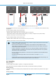
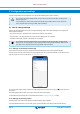
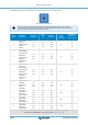
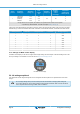
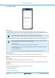
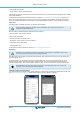
Table Of Contents
- MPPT solar charger manual
- Table of Contents
- 1. Safety precautions
- 2. Introduction
- 3. Features
- 4. Installation
- 5. Configuration and settings
- 6. Operation
- 7. Monitoring
- 8. Warranty
- 9. Troubleshooting and Support
- 9.1. The controller is not operational
- 9.2. Batteries are not charged
- 9.3. Batteries are undercharged
- 9.3.1. Too much DC load
- 9.3.2. Battery charge voltages are too low
- 9.3.3. The battery is almost full
- 9.3.4. Battery cable voltage drop
- 9.3.5. Temperature difference between solar charger and battery
- 9.3.6. Insufficient solar
- 9.3.7. Wrong temperature compensation setting
- 9.3.8. Battery charge current too low
- 9.4. Batteries are overcharged
- 9.5. Solar issues
- 9.5.1. PV reverse current too high
- 9.5.2. PV yield less than expected
- 9.5.3. Full rated output not reached
- 9.5.4. Max PV output power relates to battery voltage
- 9.5.5. Mixed PV panel types
- 9.5.6. PV connections burned or melted
- 9.5.7. MC4 connectors wrongly connected
- 9.5.8. Optimisers cannot be used
- 9.5.9. Earth fault detection missing
- 9.5.10. Ground current
- 9.6. Communication issues
- 9.7. Settings or firmware issues
- 9.8. Operation issues
- 10. Technical specifications
- 11. Appendix

Switch
position
Suggested
battery type
Absorption
voltage* (V)
Float
voltage*
(V)
Equalize**
voltage* (V)
Equalize**
nominal
current
percentage
Temperature
compensation
factor* (mV/°C)
7
Lithium Iron
Phosphate
(LiFePo4)
batteries
14.2
28.4
56.8
13.5
27.0
54
n/a n/a
0
0
0
* The top value is for 12V systems, the middle for 24V systems and the bottom for 48V systems.
** Equalize is by default disabled. To enable see chapter Battery settings [16]
A binary LED code helps determining the position of the rotary switch. After changing the position of the rotary switch, the LEDs
will blink during 4 seconds as indicated in below table. Thereafter, normal indication resumes, as described in the LEDs section.
Switch position Bulk LED Absorption LED Float LED Blinking frequency
0 1 1 1 Fast
1 0 0 1 Slow
2 0 1 0 Slow
3 0 1 1 Slow
4 1 0 0 Slow
5 1 0 1 Slow
6 1 1 0 Slow
7 1 1 1 Slow
5.1.3. Settings via MPPT Control display
The MPPT Control display can be used to configure solar charger settings, with the exception of advanced settings such as RX
and TX port settings. For information how to do this see the MPPT Control display manual.
The MPPT Control display
5.2. All settings explained
This chapter lists all solar charger settings that are user-configurable and also explains how to update firmware of the solar
charger.
Do not change settings unless you know what they are and what the effect of changing these settings will
be. Incorrect settings may cause system problems including damage to batteries. When in doubt, seek advice
from an experienced Victron Energy installer, dealer or distributor.
MPPT solar charger manual
Page 15 Configuration and settings