EN Manual NL FR DE ES SE Appendix SmartSolar charge controllers MPPT 75/10 MPPT 75/15 MPPT 100/15 MPPT 100/20 MPPT 100/20-48V
EN 1 General Description NL 1.1 Bluetooth Smart built-in: dongle not needed The wireless solution to set-up, monitor and update the controller using Apple and Android smartphones, tablets or other devices. FR 1.2 VE.Direct For a wired data connection to a Color Control panel, PC or other devices DE 1.
1.8 Three step charging The controller is configured for a three step charging process: Bulk – Absorption - Float. See section 3.8 and section 5 for default settings. See section 1.9 for user defined stings 1.8.1. Bulk During this stage the controller delivers as much charge current as possible to rapidly recharge the batteries. 1.8.2. Absorption When the battery voltage reaches the absorption voltage, the controller switches to constant voltage mode.
EN 1.9 Configuring and monitoring - Bluetooth Smart (built-in): connect to a smartphone or tablet running iOS or Android. - Use the VE.Direct to USB cable (ASS030530000) to connect to a PC, a smartphone with Android and USB On-The-Go support (requires additional USB OTG cable). - Use a VE.Direct to VE.Direct cable to connect to a MPPT Control or a Color Control panel. NL FR Several parameters can be customized with the VictronConnect app. The VictronConnect app can be downloaded from http://www.
2. IMPORTANT SAFETY INSTRUCTIONS SAVE THESE INSTRUCTIONS - This manual contains important instructions that shall be followed during installation and maintenance. Danger of explosion from sparking Danger of electric shock ● It is advised to read this manual carefully before the product is installed and put into use. ● This product is designed and tested in accordance with international standards. The equipment should be used for the designated application only.
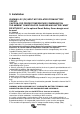
EN 3. Installation NL WARNING: DC (PV) INPUT NOT ISOLATED FROM BATTERY CIRCUIT. CAUTION: FOR PROPER TEMPERATURE COMPENSATION THE AMBIENT CONDITION FOR CHARGER AND BATTERY MUST BE WITHIN 5°C, or the optional Smart Battery Sense dongle must be used. FR DE 3.1. General ● Mount vertically on a non-flammable substrate, with the power terminals facing downwards. Observe a minimum clearance of 10 cm under and above the product for optimal cooling.
● PV voltage must exceed Vbat + 5V for the controller to start. Thereafter minimum PV voltage is Vbat + 1V. ● Maximum open circuit PV voltage: 75V respectively 100V For example: 12V battery and mono- or polycristalline panels connected to a 75V controller ● Minimum number of cells in series: 36 (12V panel). ● Recommended number of cells for highest controller efficiency: 72 (2x 12V panel in series or 1x 24V panel). ● Maximum: 108 cells (3x 12V panel in series).
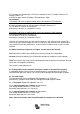
EN Some loads with high inrush current can best be connected directly to the battery. If equipped with a remote on-off input, these loads can be controlled by connecting the load output of the controller to this remote on-off input. A special interface cable may be needed. Alternatively, a BatteryProtect may be used to control the load. Please see our website for specifications. NL FR Low power inverters, such as the Phoenix VE.
3.8 Battery charging information The charge controller starts a new charge cycle every morning, when the sun starts shining.
Problem Insert 20A fuse (models 75/10, 75/15, 100/15) or 25A fuse (model 100/20) Reversed battery connection 1. 2.
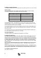
5 Specifications, 75V models SmartSolar charge controller MPPT 75/10 Battery voltage MPPT 75/15 12/24V Auto Select 10A 15A Nominal PV power, 12V 1a,b) 145W 220W Nominal PV power, 24V 1a,b) 290W 440W 13A 15A Maximum battery current Max.
SmartSolar charge controller MPPT 100/15 Battery voltage MPPT 100/20 12/24V Auto Select 20A Nominal PV power, 12V 1a,b) 220W 290W Nominal PV power, 24V 1a,b) 440W 580W 15A 20A Max. PV short circuit current 2) Automatic load disconnect Yes, maximum load 15A resp.
SmartSolar charge controller Battery voltage MPPT 100/20-48V 48V (12/24/36V: manual) Maximum battery current Nominal PV power, 48V 1a,b) 20A 1160W (290W / 580W / 870W) Max.
4. Probleemoplossing Probleem Lader werkt niet Zekering doorgebrand Mogelijke oorzaak Oplossing Omgepoolde PV aansluiting Sluit PV juist aan Geen zekering geplaatst Omgepoolde accuaansluiting Gebrekkige accuverbinding De accu wordt niet volledig geladen De accu wordt overladen Belastingsuitgang wordt niet geactiveerd 10 Plaats een 20A-zekering (modellen 75/10, 75/15, 100/15) of een 25A-zekering (model 100/20) 1. Sluit accu juist aan 2.
EN Figure 1a: configuration pins of the VE.Direct communication port, 75V models NL FR DE ES SE Appendix Figure 1b: pin numbering of the VE.
Figure 2a: configuration pins of the VE.Direct communication port, 100V models Figure 2b: pin numbering of the VE.
Figure 3: Battery management options EN FR EN: Bridge between pin 1 and 2: Low voltage disconnect: 11.1V or 22.2V Automatic load reconnect: 13.1V or 26.
Figure 4: Power connections Figure 5: The Victron inverters model Phoenix 12/800, 24/800, 12/1200 and 24/1200 can be controlled by connecting the right side connection (1) of the inverter remote control directly to the solar charger load output. Similarly, all Phoenix VE.
Victron Energy Blue Power Distributor: Serial number: Version : 08 th Date : July 24 , 2018 Victron Energy B.V. De Paal 35 | 1351 JG Almere PO Box 50016 | 1305 AA Almere | The Netherlands General phone : +31 (0)36 535 97 00 E-mail : sales@victronenergy.com www.victronenergy.