GB NL F USER MANUAL D I DK ΕΛ Phoenix Charger 12/30 12/50 24/16 24/25 N P E S Specs 0 victron energy
Copyrights 1999, 2000, 2001 Victron Energy B.V. All Rights Reserved This publication or parts thereof, may not be reproduced in any form, by any method, for any purpose. VICTRON ENERGY B.V. MAKES NO WARRANTY, EITHER EXPRESSED OR IMPLIED, INCLUDING BUT NOT LIMITED TO ANY IMPLIED WARRANTIES OF MERCHANTABILITY OR FITNESS FOR A PARTICULAR PURPOSE, REGARDING THESE VICTRON ENERGY PRODUCTS AND MAKES SUCH VICTRON ENERGY PRODUCTS AVAILABLE SOLELY ON AN “AS – IS” BASIS. IN NO EVENT SHALL VICTRON ENERGY B.V.
D I DK ΕΛ N P E Installation • The installation of this product must be performed by qualified personnel. • Always refer to the installation section in the operator’s manual before applying power to the equipment. • This is a Safety Class I product (provided with a protective earthing terminal). An uninterruptible safety earth ground must be provided at the AC in/output terminals. An additional grounding point is located at the outside of the product.
To keep your batteries in shape the Phoenix Charger will raise the applied voltage once a week. This we call the repetitive absorption. DESCRIPTION Technology The Phoenix Charger is a fully high-frequency switched battery charger. The input is electronically powerfactor corrected by the first powerstage. The next stage gives provision for galvanic isolation and a perfect DC voltage at the output terminals.
Float I Failure TROUBLESHOOTING Problem Failure LED illuminates Make sure the charger matches the battery capacity The output fuses are Return the product to your defect dealer The Absorption Consult your battery voltage is wrongly supplier and electrician and adjusted have the charging voltage The float voltage is adjusted wrongly adjusted A single battery cell Replace the battery or the is defect defect cell Too small a battery Consult your battery supplier and electrician and have the charging curren
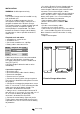
INSTALLATION WARNING: Qualified personnel only Location The Phoenix Charger must be installed in a dry, well-ventilated area. Too high an ambient temperature has the consequence of lower output, shorter life or a complete shutdown of the Phoenix Charger. The Phoenix Charger is suitable for floor and wall mounting. However, for optimum cooling, a vertical position is recommended. The cables between the Phoenix Charger and the battery must be kept as short as possible to minimise cable losses.
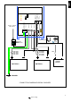
+ Trickle charge Trickle charge - battery + battery 1 Remote Connector <==> 20AT 20AT 20AT 20AT POLARITY + battery 2 L AC input : Line N AC input : Neutral - D PE earth connection - F 120Vac – 240Vac Mains input NL + Voltage sense Voltage sense + Temperature sense Temperature sense GB - PHOENIX CHARGER CONTROL I 25AT N BATTERY 2 12/50: 60AT 12/30: 40AT 24/25: 30AT 24/16: 20AT 5AT ΕΛ 12/50: 60AT 12/30: 40AT 24/25: 30AT 24/16: 20AT DK DOUBLE POLE SWITCH & CIRCUIT BREAKER STARTER
Adjustments without remote panel When ready • Connect battery and if applicable Voltage sense and Temperature sense. • Replace the frontplate.
Adjustments with remote panel Phoenix Charger Control WARNING: Always check with your battery supplier if the choosen charge characteristic is suitable for your battery and application • Remove the frontplate and connect the Phoenix Charger Control panel to the 8-pin modular jack. • Disconnect battery, Voltage sense and Temperature sense. A voltmeter is not required but may be useful. • While switching on keep one of the pushbuttons ⇑ & ⇓ pushed. • Release pushbutton.
After 4 hours the charger continues the normal sequence with the old value. This could be useful if a forced high voltage is wanted to get some life in an assumed ‘dead’ battery. Return to factory defaults • Switch the charger on. • Keep the pushbutton ⇑ and/ or ⇓ pushed while switching off. • The factory defaults are restored. • Replace the frontplate.
GB SPECIFICATIONS @ Vin=230Vac/Vout=12Vdc/Ta=25°C @ Vin=230Vac/Vout=24Vdc/Ta=25°C 50 Adc 1 - 50 Adc 30Adc 1 - 30 Adc 25 Adc 1 - 25 Adc 4 Adc 16 Adc 1 - 16 Adc 4 Adc ±1% 4x 20 A carfuse 2x 20 A carfuse DK <2 mA 200 - 400 Ah 100 - 200 Ah 100 - 200 Ah 45 - 100 Ah EEC 89/336 EN55014 (1993) EN61000-3-2 EN61000-3-3 EN55104 (1995) EN60335-2-29 (1991) IEC68-2-6 : 10 - 150 Hz / 1.0 G IEC68-2-29: 1000 times XYZ +/- 10 G / 16 ms 0-40°C -20 - +60°C max.
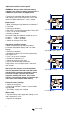
Charge current 120% 100% 80% Amps 60% 40% 20% 0% Time Volts Charge voltage 30 16 29 28 27 15 Battery Safe mode 5 x Bulk-hours or Max. Absorption time 14 26 25 13 24 23 22 12 11 21 20 10 Bulk-hours Absorption time 1 day Float 7 days reduced Float 7 days reduced Float Time 1 hour Repeated Absorption Figure 1: Adaptive charging: Bulk-mode: Entered after a reset or if the battery voltage becomes 1.3V resp. 2.6V (for 12V and 24V charger) lower than Float voltage.
GB 5 D 0 Volts F 30 29 28 27 26 25 24 23 22 21 20 NL 15.0 14.5 14.0 13.5 13.0 Volts 12.5 12.0 11.5 11.0 10.5 10.0 10 15 20 25 30 35 40 45 50 55 60 Battery temperature Figure 2: Temperature compensation I Default output voltages for Float and Absorption are at 20°C. In adjust mode temperature compensation does not apply. DK 100% 95% ΕΛ Tamb = 25°C 90% 85% 80% Am ps 75% Tamb = 40°C 70% N 65% 60% 55% 50% 90 110 120 132 150 170 187 230 P U in Figure 3: Maximum output current vs.
Default factory settings: Repeated Absorption interval Repeated Absorption time Maximum Absorption time Characteristic: Default = 3 7 days 4 quarters of an hour 4 hrs Absorption time 1 = Fixed Repeated Absorption interval Repeated Absorption time 4 hrs 1 day 2 quarters 2 = Adaptive 3 = Adaptive with Battery Safe Mode Battery type: Default = 1 0:User defined 1: Sonnenschein Dryfit A200 Gel 2: Traction (Tubular plate) 3: Semitraction 4: Victory Abs. Voltage 14.4 V 15.0 V 14.4 V 14.8 V 12V model 28.