Manual EN Handleiding NL Manuel FR Anleitung DE Manual ES Användarhandbok SE Appendix BlueSolar charge controllers MPPT 100/30 MPPT 100/50
1. General Description EN NL 1.1 PV voltage up to 100V The charge controller is able to charge a lower nominal-voltage battery from a higher nominal voltage PV array. The controller will automatically adjust to a 12 or 24V nominal battery voltage. FR 1.
1.8 Flexible charge algorithm Fully programmable charge algorithm, and eight preprogrammed algorithms, selectable with a rotary switch. 1.9 Adaptive three step charging The Controller is configured for a three step charging process: Bulk – Absorption – Float. 1.9.1. Bulk During this stage the controller delivers as much charge current as possible to rapidly recharge the batteries. 1.9.2.
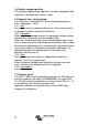
EN 1.11 Configuring and monitoring - Bluetooth Smart (built-in): connect to a smartphone or tablet running iOS or Android. - Use the VE.Direct to USB cable (ASS030530000) to connect to a PC, a smartphone with Android and USB On-The-Go support (requires additional USB OTG cable). - Use a VE.Direct to VE.Direct cable to connect to a MPPT Control, a Color Control panel or the Venus GX. NL FR Several parameters can be customized with the VictronConnect app.
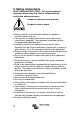
2. Safety instructions SAVE THESE INSTRUCTIONS - This manual contains important instructions that shall be followed during installation and maintenance. Danger of explosion from sparking Danger of electric shock ● Please read this manual carefully before the product is installed and put into use. ● This product is designed and tested in accordance with international standards. The equipment should be used for the designated application only. ● Install the product in a heatproof environment.
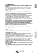
3. Installation EN WARNING: DC (PV) INPUT NOT ISOLATED FROM BATTERY CIRCUIT. CAUTION: FOR PROPER TEMPERATURE COMPENSATION THE AMBIENT CONDITION FOR CHARGER AND BATTERY MUST BE WITHIN 5°C. 3.1. General ● Mount vertically on a non-flammable substrate, with the power terminals facing downwards. Observe a minimum clearance of 10 cm under and above the product for optimal cooling. ● Mount close to the battery, but never directly above the battery (in order to prevent damage due to gassing of the battery).
WARNING: WHEN A GROUND FAULT IS INDICATED, BATTERY TERMINALS AND CONNECTED CIRCUITS MAY BE UNGROUNDED AND HAZARDOUS. 3.3 PV configuration (also see the MPPT Excel sheet on our website) ● Provide a means to disconnect all current-carrying conductors of a photovoltaic power source from all other conductors in a building or other structure.
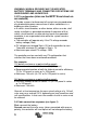
Pos 4 7 -32 Gel Victron deep discharge 32,2 28,6 27,6 -32 Gel Exide A200 @8% AGM Victron deep discharge Stationary tubular plate (OPzS) Default setting 32,4 Gel Victron deep discharge 28,8 27,6 -32 @8% Gel Exide A200 AGM Victron deep discharge Stationary tubular plate (OPzS) AGM spiral cell 33,0 -32 29,4 27,6 Stationary tubular plate (OPzS) @8% Rolls AGM PzS tubular plate traction 33,4 -32 29,8 27,6 batteries or @25% OPzS batteries PzS tubular plate traction 33,8 -32 30,2 27,6 batteries or @25% OPzS bat
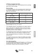
On all models with software version V 1.12 or higher a binary LED code helps determining the position of the rotary switch. After changing the position of the rotary switch, the LEDs will blink during 4 seconds as follows: Switch position 0 1 2 3 4 5 6 7 LED Bulk 1 0 0 0 1 1 1 1 LED Abs 1 0 1 1 0 0 1 1 LED Float 1 1 0 1 0 1 0 1 Blink frequency Fast Slow Slow Slow Slow Slow Slow Slow Thereafter, normal indication resumes, as described below.
EN 3.7 Battery charging information The charge controller starts a new charge cycle every morning, when the sun starts shining.
3.8 Automatic equalization Automatic equalization is default set to ‘OFF’. With the Victron Connect app (see sect 1.10) this setting can be configured with a number between 1 (every day) and 250 (once every 250 days). When automatic equalization is active, the absorption charge will be followed by a voltage limited constant current period. The current is limited to 8% of the bulk current for the factory default battery type, and to 25% of the bulk current for a user defined battery type.
4. Troubleshooting EN Problem Solution Reversed PV connection Connect PV correctly Reverse battery connection Non replacable fuse blown. Return to VE for repair Check battery connection Only for a 24V system: wrong system voltage chosen (12V instead of 24V) by the charge controller Set the controller manually to the required system voltage (see section 1.
5. Specifications BlueSolar Charge Controller Battery voltage Rated charge current Nominal PV power, 12V 1a,b) Nominal PV power, 24V 1a,b) Maximum PV open circuit voltage Max.
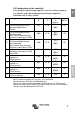
EN Figure 1: Power connections NL FR DE ES SE Appendix
Victron Energy Blue Power Distributor: Serial number: Version Date : 06 : September 21st.