ENGLISH MPPT solar charger manual SmartSolar MPPT 150/60 up to 250/70 03/2021
MPPT solar charger manual Table of Contents 1. Safety precautions ................................................................................................................... 1 1.1. General safety precautions ................................................................................................. 1 1.2. Wiring safety precautions ................................................................................................... 2 2. Introduction ..............................................
MPPT solar charger manual 7.1. LED indications ............................................................................................................ 7.2. Error codes ................................................................................................................. 7.3. Monitoring via the VictronConnect App ................................................................................. 7.3.1. VictronConnect status screen ...............................................................
MPPT solar charger manual 11. Appendix ........................................................................................................................... 59 11.1. Dimensions 60A-MC4 and 70A-MC4 SmartSolar .................................................................... 59 11.2. Dimensions 60A-Tr and 70A-Tr SmartSolar ........................................................................... 60 11.3. Charger error code overview ..................................................................
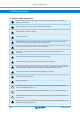
MPPT solar charger manual 1. Safety precautions 1.1. General safety precautions Read this manual carefully. It contains important instructions that need to be followed during installation, operation and maintenance. Save these instructions for future reference on operation and maintenance Danger of battery explosion from sparking Danger of electric shock Install the product in a heatproof environment. Ensure therefore that there are no chemicals, plastic parts, curtains or other textiles, etc.
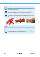
MPPT solar charger manual 1.2. Wiring safety precautions Use flexible multi-stranded copper cable for the battery and PV connections. The diameter of the individual strand of the cable used should not exceed 0.4mm (0.016 inch) or have a surface area exceeding 0.125mm² (AWG26). A 25mm² cable, for example, should have at least 196 strands (class 5 or higher stranding according to VDE 0295, IEC 60228 and BS6360). An AWG2 gauge cable should have at least 259/26 stranding (259 strands of AWG26).
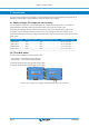
MPPT solar charger manual 2. Introduction The Victron Energy SmartSolar charge controller is an ultra fast Maximum Power Point Tracking (MPPT) solar charger with an outstanding conversion efficiency and is suitable for a wide range of battery and PV voltages. 2.1. Battery voltage, PV voltage and current rating The solar charger can charge a lower nominal-voltage battery from a higher nominal voltage PV array.
MPPT solar charger manual 3. Features 3.1. Automatic battery voltage detection The solar charger automatically detects a 12, 24 or 48V system voltage (battery voltage) on first power up. If a different system voltage is required at a later stage, or if the solar charger is connected to a 36V system, this can be manually configured in the solar charger settings. 3.2. Outstanding MPPT algorithm Ultra fast MPP tracking The solar charger contains an ultra fast MPPT controller.
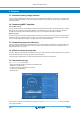
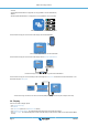
MPPT solar charger manual • • • • Android Apple iOS (Note that USB is not supported, it is only possible to connect via Bluetooth) MacOs Windows (Note that Bluetooth is not supported, it is only possible to connect via USB) Where to download the VictronConnect App from The VictronConnect App can connect to the solar charger via its built-in Bluetooth. VictronConnect App connection via built-in Bluetooth The VictronConnect App can connect to the solar charger via the VE.Direct USB interface.
MPPT solar charger manual 3.7. VE.Direct port The VE.Direct port is used to communicate with the solar charger. It can be used for several purposes: • To connect to a monitoring device, such as a GX device or the GlobalLink. • To connect with the VictronConnect App. • For external control. Special cables or interfaces are needed to connect to this port: • • • • • VE.Direct cable - used to connect to a GX device or the GlobalLink. VE.
MPPT solar charger manual The internal temperature is used to set the temperature compensated charge voltages. For this, the internal temperature when the solar charger is "cold" is used. The solar charger is "cold" when there is only little current flowing into the battery. Be aware that this is only an estimation of the ambient and the battery temperature.
MPPT solar charger manual • When the voltage on the H terminal is more than 2.9V (up to the battery voltage) via a switch, relay or other external device, like a battery BMS. • When the voltage on the L terminal is pulled to battery minus. (<3.5V) via a switch, relay or other external device, like a battery BMS. A virtual remote on/off terminal can be created by using the VE.Direct non inverting remote on/off cable. The functionality can be programmed using the VictronConnect App RX port function settings.
MPPT solar charger manual 4. Installation The DC (PV) input is not isolated from the battery circuit. Therefore the PV, battery and control circuit are considered hazardous and should not be user accessible. For proper temperature compensated battery charging the ambient temperature of the solar charger and the battery must be within 5°C (9°F). The battery and PV connections must be guarded against inadvertent contact. Install the solar charger in an enclosure or install the optional WireBox [8]. 4.1.
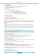
MPPT solar charger manual 120 W 12 V 120 W 12 V 240 W 24 V 10 A 120 W 12 V 120 W 12 V 120 W 12 V 120 W 12 V 240 W 12 V 20 A 120 W 12 V 120 W 12 V 480 W 24 V 20 A Examples of series, parallel and series/parallel solar arrays. To help calculate the size of the PV array configuration use the MPPT sizing calculator.
MPPT solar charger manual Apply a single ground connection, preferably close to the battery, to prevent system issues or ground loops. Chassis grounding A separate ground path for the chassis ground is permitted because the chassis is isolated from the positive and the negative terminals. PV array grounding The positive and negative of the PV array should not be grounded. Ground the frame of the PV panels to reduce the impact of lightning. Do not connect the solar charger to a grounded PV array.
MPPT solar charger manual 4.6. Install the optional SmartSolar Control display To install the optional SmartSolar Control display follow these steps: 1. 2. 3. 4. 5. 6. Remove the two screws of the plastic cover. Keep the screws, they are needed again when securing the display. Remove the plastic cover. The display terminal is now exposed. Remove the two plastic plugs on either side of the display plug. Remove the paper backing of the double sided tape on the back of the display.
MPPT solar charger manual VE.Direct cable Connect the display to the solar charger via a VE.
MPPT solar charger manual 5. Configuration and settings The solar charger settings can be configured so it can be taylored specifically for the system it is used in. Do not change solar charger settings unless you know what they are and what the effect of changing these settings is going to be. Incorrect settings may cause system problems including damage to batteries. When in doubt, seek advice from an experienced Victron Energy installer, dealer or distributor. 5.1.
MPPT solar charger manual The table below indicates the charge algorithm and charge settings for each rotary switch position. Rotary switch set to position 2 Turning the rotary switch will override the charge settings including settings that were made with the VictronConnect App or with the display. Likewise, if charge settings are changed with the VictronConnect App or the display, this will override the rotary switch setting.
MPPT solar charger manual Switch position Suggested battery type Absorption voltage* (V) Float voltage* (V) 14.2 13.5 7 Lithium Iron Phosphate (LiFePo4) batteries 28.4 27.0 56.8 54 Equalize** voltage* (V) Equalize** nominal current percentage n/a n/a Temperature compensation factor* (mV/°C) 0 0 0 * The top value is for 12V systems, the middle for 24V systems and the bottom for 48V systems. ** Equalize is by default disabled.
MPPT solar charger manual Do not change settings unless you know what they are and what the effect of changing these settings will be. Incorrect settings may cause system problems including damage to batteries. When in doubt, seek advice from an experienced Victron Energy installer, dealer or distributor. 5.2.1. Battery settings Battery voltage The battery voltage is automatically detected at the very first power-up of the solar charger and the battery voltage is set accordingly.
MPPT solar charger manual • • • • The rotary switch position Pre-defined factory battery presets User defined battery presets Create, modify or delete a user defined preset. This setting uses factory pre-defined presets for a large variety of battery types. These pre-defined charge algorithms are suitable for almost all installations. It is possible to also create user-defined battery presets. The chapter Customize battery charge algorithm [18] explains how to do this.
MPPT solar charger manual Only experienced users should configure or edit user defined battery charge algorithms. A wrongly defined battery charge algorithm can lead to battery damage or create unsafe situations. To Modify a basic battery charge algorithm: • • • • Select a preset battery type that is the best match to your battery type. Change one of the basic charge parameters that are listed on the settings screen. Configure the required parameters. The battery preset is now set to "user defined".
MPPT solar charger manual This setting sets the absorption voltage. Adaptive absorption time This setting enables or disables the adaptive absorption time. • When disabled: The length of the absorption stage is the same each day, the length is determined by the "Maximum absorption time" setting, provided there is enough solar power. Be aware that this option can potentially result in overcharging your batteries, especially for lead batteries and if only shallow daily discharges take place.
MPPT solar charger manual • For all VRLA battery presets and for some flooded batteries presets, the automatic equalization stage ends when the voltage limit (maxV) has been reached, or after a period equal to absorption time/8, whichever comes first. • For all tubular plate battery presets and for user-defined battery types, the automatic equalization stage ends when the time has reached absorption time/2. • For the lithium battery preset, equalization is not available.
MPPT solar charger manual The "Low temperature cut-off" feature is only active when the solar charger is part of a VE.Smart Network and is receiving a battery temperature reading from a BatterySense or a battery monitor with temperature sensor. The "low temperature cut-off" setting is by default disabled. When enabled, a low cut off temperature can be set. The default temperature is 5°C, this is a suitable temperature setting for lithium iron phosphate (LFP) batteries.
MPPT solar charger manual The load output settings also controls the streetlight algorithm. Both work together to protect the battery from being too deeply drained. The streetlight settings are overridden should the battery voltage falls below the load disconnect voltage. When the battery voltage increases to the load reconnect voltage, the streetlight function will resume. 5.2.3. Programmable relay settings The programmable relay can be configured to a variety of relay modes.
MPPT solar charger manual Relay mode Description and notes Panel voltage high This option switches the relay ON when the panel voltage becomes too high. High temperature (Dimming) This option switches the relay ON when the charger output current is reduced due to high temperatures. Use this option to for example switch an external fan. Battery voltage Low This option switches the relay in ON when the battery voltage falls too low, This is the default setting when the relay function is active.
MPPT solar charger manual Streetlight control The solar charger controls the streetlight: • Via the TX port together with a VE.Direct TX digital output cable. Also see the TX port settings [27] chapter for more details. • Via the programmable relay. Also see the Programmable relay settings [23] chapter for details.
MPPT solar charger manual • Switch off: Turns the light off at sunrise • Switch on before sunrise: This option switches the light on at a configurable time interval before sunrise, and then switches the light off at sunrise. In case the dimming feature is enabled1 an interval of more intense light can be configured during early morning rush hour.
MPPT solar charger manual • The night duration in minutes is: 1440m(min/day) -1140m(time to sunset) + 385m(time to sunrise) = 685m • The degree of shift = time of sunset(minutes) + half the duration of night(minutes) - length of day(minutes) = 1140m + 342m - 1440m = 42 minutes.
MPPT solar charger manual The functionality of the TX port can be set at: • Normal communication: This is the default setting. Use this function when connecting to a GX device, a VE.Direct Bluetooth Smart dongle, or any other device that needs to communicate with the solar charger via the VE.Direct port. • Pulse every 0.01 kWh: Use this function in combination with an energy meter. The TX port will emit a pulse each time an additional 0.01kWh of energy has been harvested.
MPPT solar charger manual - RX pin +5V will switch load output off • Load output on/off normal: This setting allows load output on/off control: - RX pin 0V will switch the load output off - RX pin +5V will switch load output on For more in depth "developer style" information on the VE.Direct port see the Data communication with Victron Energy products Whitepaper. 5.3. Updating firmware The firmware can be checked and updated with VictronConnect.
MPPT solar charger manual • Battery voltage sensing - the measured battery voltage is used by the chargers in the network to to compensate the charge voltage should there be a voltage drop over the battery cables. • Current sensing - The measured battery current is used by the charger so it knows the exact tail current at which the absorption stage should end and the float (or equalisation) stage should start.
MPPT solar charger manual To check if an individual device is communication with the network, click on the VE.Smart symbol in the main screen next to the solar dail. A pop-up window will open showing teh connection status and the shared parameters. VE.Smart network pop-up To check if all devices are actively communication to the same VE.Smart network, navigate to the settings page of one of the networked devices and click on "VE.Smart networking".
MPPT solar charger manual 6. Operation 6.1. Start up The solar charger will power up as soon as it has been connected to a battery and/or to a solar panel. As soon as the solar charger has been powered up, it can communicate via the VE.Direct port and Bluetooth. The the solar charger's data can be read out and setting configurations can be made using the VictronConnect or the optional display. The solar charger will commence battery charging as soon as the PV voltage is 5V higher than the battery voltage.
MPPT solar charger manual • Absorption time determined by tail current: In some applications it may be preferable to terminate absorption time based on tail current only. This can be achieved by increasing the default absorption time multiplier (warning: the tail current of lead-acid batteries does not decrease to zero when the batteries are fully charged, and this “remaining” tail current can increase substantially when the batteries age).
MPPT solar charger manual 7. Monitoring This chapter describes all various monitoring methods and for each method how to access live data, historic data and errors. 7.1. LED indications The solar charger has three LEDs to indicate operational status, a blue, green and a yellow LED. These LEDs respectively indicate the charge stages bulk, absorption and float, but are also used to indicate other charge situations and fault situations.
MPPT solar charger manual 7.2. Error codes In case of an error, an error code will be displayed via VictronConnect, a display, a GX device or on VRM. Each number corresponds with a specific error. For a full list of error codes and their meaning see the appendix: Charger error code overview [61]. 7.3. Monitoring via the VictronConnect App The VictronConnect App can be used to monitor the solar charger, see its historical values and if there are operational warnings or errors.
MPPT solar charger manual charger will enter the Float stage. Note that when an automatic equalisation is being performed this will also be reported as absorption. Float During this stage the float voltage is applied to the battery to maintain a fully-charged state. When the battery voltage drops below float voltage during at least 1 minute, a new charge cycle will be triggered.
MPPT solar charger manual The history can be exported as a comma separated file (CSV) by clicking the three connected dots symbol or the save symbol at the top right of the history screen. The symbol varies, depending on what platform VictronConnect is used. The history can be reset by clicking the clock with arrow symbol at the top right of the history screen. 7.3.3. VictronConnect error reporting VictronConnect will indicate active errors while VictronConnect is actively connected to the solar charger.
MPPT solar charger manual 8. Warranty This product has a 5-year limited warranty. This limited warranty covers defects in materials and workmanship in this product and lasts for five years from the date of original purchase of this product. To claim warranty the customer must return the product together with the receipt of purchase to the point of purchase.
MPPT solar charger manual 9. Troubleshooting and Support Consult this chapter in case of unexpected behaviour or if you suspect a product fault. The correct troubleshooting and support process is to first consult the common issues as described in this chapter. Should this fail to resolve the issue, contact the point of purchase for technical support. If the point of purchase is unknown, refer to the Victron Energy Support webpage. 9.1.
MPPT solar charger manual Battery voltage Operational state Action to take Correct Voltage Powered, but not charging Connect PV supply and check if battery charging starts. If charging does not start, see chapter: “ Batteries are not charged”. 9.2. Batteries are not charged This chapter lists all possible reasons why the solar charger does not charge the batteries, and the steps you can take to remedy the situation. There are a number of reasons why the solar charger might not charge the batteries.
MPPT solar charger manual Reverse battery polarity can in rare occasions be accompanied with a blown battery fuse (one that is located in the battery cable). But in most cases the ultra-fast internal fuse inside the solar charger will blow to ensure a proper fail-safe situation. This internal fuse will usually blow before the external fuse blows. The internal fuse is located in a non-serviceable area of the solar charger. It is not possible to replace or repair this fuse.
MPPT solar charger manual VictronConnect charger enable/disable setting 9.2.6. PV voltage too low The solar charger will commence charging when the PV voltage is 5V higher than the battery voltage. Once charging has commenced, the PV voltage must remain 1V higher than the battery voltage for charging to continue. Check the PV and battery voltage WARNING: Depending on the solar charge controller model, the PV voltage can be up to 250Vdc. Voltages above 50V are generally considered to be dangerous.
MPPT solar charger manual 9.2.7. Battery voltage setting too low The battery will not be charged if the “battery voltage” setting in the VictronConnect App is set at a voltage lower than the actual system voltage. Check that the battery voltage is set properly in the settings of the solar charger. The battery voltage setting has to match that of the voltage of the battery.
MPPT solar charger manual 2. Use a multi meter to measure the voltage at the battery terminals. V 3. 4. Compare the two voltages. If the battery voltage and the controller voltage are not the same, then investigate why this is. Follow the path from the controller to the battery to investigate what could be the cause. Battery supply check 1. 2. 3. 4. Check and verify that all cabling is connected correctly, and that no wiring mistakes have been made.
MPPT solar charger manual 9.3. Batteries are undercharged This chapter deals with possible reasons why the solar charger is not sufficiently charging the batteries and the steps you can take to check or remedy the situation. Some signs of undercharged batteries: • The batteries take too long to charge. • The batteries are not fully charged at the end of the day. • The charge current from the solar charger is less than expected. 9.3.1.
MPPT solar charger manual • Loose terminal connections • Bad or loose fuse(s) For more information on cabling issues and voltage drop see the Wiring unlimited book Battery cable voltage drop check This check can only be performed if the solar charger is in the bulk charge stage and is charging with full current. 1. Measure the voltage on the battery terminals of the solar charger using the VictronConnect App or a multi meter. V OR 2.
MPPT solar charger manual • • • • Not enough solar panels Too much load A problem with the array causing it to have a reduced power output. For more potential reasons see paragraph: “PV power or yield less than expected” Please note that above information does not apply to an ESS system. An ESS system will always be in the bulk charge stage while grid is connected. System spending all its time in bulk with breakdown of charge stages - System in bulk and absorption 9.3.7.
MPPT solar charger manual 9.4.2. Battery charge voltages too high If the battery charge voltages are set too high this will cause the batteries to overcharge. Check if all the battery charge voltages (absorption and float) are set correctly. The charge voltages have to match the recommended voltages as stated in the battery manufacturers documentation. 9.4.3.
MPPT solar charger manual 2. Check if the battery has been charged with a too high voltage. Very high charge voltage will damage the battery. Check the maximum battery voltage and the high voltage alarms in the battery monitor. Check if the measured maximum voltage has exceeded the battery manufacturer recommendations. 9.5. Solar issues This chapter deals with the remaining potential solar issues that were not already discussed in the earlier chapters. 9.5.1.
MPPT solar charger manual PV array too small If the PV array power rating is less than the solar charger nominal power rating, the solar charger cannot output more power than the connected solar array can provide. Temperature above 40°C When the solar charger heats up, eventually the output current will derate. When the current is reduced naturally the output power will reduce as well. The controller is operational up to 60°C, with a full rated output up to 40°C.
MPPT solar charger manual • • • • Loose screw connection. Cable insulation inserted too deep into the connector. Cables with rigid core wire or rigid strands used. Cables where the core wire has been soldered. MC4 terminals • Current has exceeded 30A per connector pair. • Incorrectly crimped MC4 connectors. • Bad quality MC4 connectors used 9.5.7.
MPPT solar charger manual 9.6.3. VE.Smart communication issues A VE.Smart Network is a wireless communication network between several Victron products using Bluetooth. In case of issues with a VE.Smart Network refer to the Smart Network manual. 9.6.4. Bluetooth issues Please note that it is highly unlikely that the Bluetooth interface is faulty. The problem is most likely caused by something else. Use this chapter to quickly rule out some of the common causes of Bluetooth issues.
MPPT solar charger manual NOTE: It might be usefull to write down the firmware number before and after the update. This can be usefull information should you need to request support. On first connection, the controller might have updated the firmware. If the controller did not automatically ask for a firmware update, check if the controller is running the most up to date firmware and perform a manual update: • Connect to the controller. • Click on the settings symbol • • • • . Click the option symbol .
MPPT solar charger manual Use VictronConnect to check the relay functionality setting. When checking the relay check if the relay contacts are opened and closed when the relay is energized and also when the relay is not energized. The relay gets damaged if a circuit with a current larger than 8A is connected to the relay contacts. This is not covered by warranty.
MPPT solar charger manual 10. Technical specifications 10.1. Specifications 150/60 and 150/70 MPPT 150/60 Battery voltage Maximum battery current MPPT 150/70 12/24/48V Auto select, 36V: manual select 60A 70A Nominal PV power, 12V 1a,b 860W 1000W Nominal PV power, 24V 1a,b 1720W 2000W Nominal PV power, 36V 1a,b 2580W 3000W Nominal PV power, 48V 1a,b 3440W 4000W Max.
MPPT solar charger manual MPPT 150/60 MPPT 150/70 1a) The solar charger will limit input power if more PV power is connected. 1b) The PV voltage must exceed Vbat + 5V for the controller to start. Thereafter the minimum PV voltage is Vbat + 1V. 2) A higher short circuit current may damage the solar charger in case of reverse polarity connection of the PV array. 3) Equalization is by default disabled.
MPPT solar charger manual 10.2. Specifications 250/60 and 250/70 MPPT 250/60 Battery voltage MPPT 250/70 12/24/48V Auto select, 36V: manual select Maximum battery current 60A 70A Nominal PV power, 12V 1a,b 860W 1000W Nominal PV power, 24V 1a,b 1720W 2000W Nominal PV power, 36V 1a,b 2580W 3000W Nominal PV power, 48V 1a,b 3440W 4000W Max.
MPPT solar charger manual MPPT 250/60 MPPT 250/70 1a) The solar charger will limit input power if more PV power is connected. 1b) The PV voltage must exceed Vbat + 5V for the controller to start. Thereafter the minimum PV voltage is Vbat + 1V. 2) A higher short circuit current may damage the solar charger in case of reverse polarity connection of the PV array. 3) Equalization is by default disabled.
MPPT solar charger manual 11. Appendix 11.1. Dimensions 60A-MC4 and 70A-MC4 SmartSolar 1 2 3 4 6 5 7 8 Dimension Drawing - SmartSolar charge controller SCC115045310 SCC115060310 SCC115070310 A 250 SmartSolar MPPT 150/45-MC4 SmartSolar MPPT 150/60-MC4 SmartSolar MPPT 150/70-MC4 A 91 228 4 A R2.75 35 B 5.
MPPT solar charger manual 11.2. Dimensions 60A-Tr and 70A-Tr SmartSolar 1 2 3 4 6 5 7 8 Dimension Drawing - SmartSolar charge controller SCC115045210 SCC115060210 SCC115070210 A SmartSolar MPPT 150/45-Tr SmartSolar MPPT 150/60-Tr SmartSolar MPPT 150/70-Tr A 250 228 91 4 B R2.75 A 5.
MPPT solar charger manual 11.3. Charger error code overview This overview lists all possible error codes that can be generated by a solar charger or AC charger. The error codes are displayed on the charger display, remote display or via a connected GX device. Note that not all of these errors might apply to your charger model. Some error types only apply for solar chargers, for AC chargers or are specific only to certain models within a charger group.
MPPT solar charger manual Power terminals overheated, check wiring, including the wiring type and type of strands, and/or fasten bolts if possible. This error will auto-reset. Error 28 - Power stage issue This error will not auto-reset. Disconnect all wires, and then reconnect all wires. If the error persists the charger is probably faulty. Note that this error was introduced in v1.36. So when doing an update, it might look like the firmware update caused this issue; but it doesn't.
MPPT solar charger manual Check the connection between the charger and the BMS. How to reconfigure the charger to standalone mode: The charger automatically configures themselves to be BMS-controlled when they are connected to one; either direct or via a GX Device. And that setting is semi-permanent: power cycling the charger will not reset it. Here is what needs to be done to make the charger operate in stand-alone mode again, ie. not controlled by a BMS: • VE.