ENGLISH Skylla-IP65 Rev 02 02/2021
Skylla-IP65 Table of Contents 1. Safety Instructions ................................................................................................................... 1 1.1. General ....................................................................................................................... 1 1.2. Installation .................................................................................................................... 1 1.3. Transport and storage .........................................
Skylla-IP65 1. Safety Instructions 1.1. General • Please read the documentation supplied with this product first, so that you are familiar with the safety signs and directions before using the product. • This product is designed and tested in accordance with international standards. The equipment should be used for the designated application only. danger of electric shock • The product is used in combination with a permanent energy source (battery).
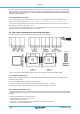
Skylla-IP65 2. Installation and wiring 2.1. Installation Find a dry and well-ventilated area to mount the Skylla-IP65 charger and battery. Keep the cable length between the charger and the battery less than 6 meters. The charger may be wall or floor mounted. Always make sure that air may flow freely at the back side of the cabinet. This will improve cooling of the charger and prolong lifetime. Wall mounting The unit can best be mounted vertical to a wall.
Skylla-IP65 The Skylla-IP65 is NOT protected against reverse polarity of the main battery. ("+" connected to "-" and "-" connected to "+"). Follow the installation procedure. The warranty expires when the Skylla-IP65 becomes defective due to reverse polarity. Disconnect the mains supply before making or breaking connections to the main battery. 1. Disconnect the mains supply 2. Disconnect battery cables from the battery. 3.
Skylla-IP65 current of one charger may differ from another charger although connected in parallel.In case of using remote sensors (voltage and/or temperature), the remote sensor needs to be connected to one of the parallel operating chargers. All other chargers will share the information via the CAN interface. In case of synchronised parallel operation, the network icon will blink every 3 seconds on all paralleled units. 2.4.2.
Skylla-IP65 2.5.3. Remote shut down From factory the remote + and - are connected together with a jumper wire to turn the charger on. In order to use the remote to shutdown the charger, remove the jumper and connect a wire to "remote -" input. Switching the "remote -" input to battery voltage causes the charger to turn on. This wire can be used to connect to a BMS used for lithium batteries to control the charger. 2.5.4.
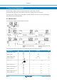
Skylla-IP65 3. Control and Adjustment When the charger is installed correctly, the charger should be set up to suit the battery connected. To set up the charger, apply mains power and enter the setup menu by pressing “SETUP” for three seconds. The charger will enter a standby mode (no power applied to the battery terminals) and the user can set up the unit accordingly. See the next table for all possible adjustments. 3.1. Monitor menu The monitor menu is visible when power is applied to the charger.
Skylla-IP65 Displayed info Battery charge current out Icons Segments 3*2 3 Warning message*3 *4 Error message*3 *4 Units A 60.0 1 nF 65 Err 2 BMS operation*3 BMS *1 A valid temperature is shown. “ --- “ means no sensor information or “Err” means invalid sensor data. *2 The output channel number is shown in the first segment; only visible in a three output model. *3 These items are only visible when relevant. *4 After a short delay a scrolling text is shown with the error description.
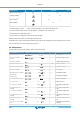
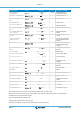
Skylla-IP65 Scrolling text Icons Segments 20 TEMPERATURE COMPENSATION -3.0-2.7-0.0 22 BULK TIME PROTECTION OFF10 23 MAXIMUM ABSORPTION TIME 1.0-8.024.0 Units Function or parameter °C mV Battery temperature compensation per cell A Bulk time protection h Absorption time 24 STORAGE MODE On, OFF 25 MAXIMUM FLOAT TIME 4.0-8.0-24.0 h Maximum float time 26 REPEATED ABSORPTION TIME 0.5-1.0-24.0 h Repeated absorption time 27 REPEATED ABSORPTION TIME INTERVAL 0.5-7.
Skylla-IP65 3.3. Battery selection The charge algorithm of the charger must fit the battery type connected to the charger. The following table shows all the predefined battery types available in the charge algorithm selection menu. # Description Unit type Absorption Float Storage Equalization V V V Max V @% of Inom dV/d T mV/° C 1 Gel Victron long life (OPzV) 12 V 14.1 13.8 13.2 15.9 @ 6 % max 1hr -16 Gel exide A600 (OPzV) 24 V 28.2 27.6 26.4 31.
Skylla-IP65 The temperature sensor must be installed when: • ambient temperature of the battery is expected to regularly be lower than 15 °C or to regularly exceed 30 °C • charge current exceeds 15 A per 100 Ah battery capacity Temperature compensation is not required for Li-Ion batteries. 3.6. Power Control – maximum use of limited shore current A maximum mains current can be set in order to avoid interruption of an external fuse in the mains supply.
Skylla-IP65 4. Operation 4.1. Battery charging After applying mains power and remote shut down is not active, the display will show the following: All icons of the screen will be visible to check the correct functioning of the display. • • • • The back lighting of the display is ON. Next the firmware version number will be displayed. Finally, the actual state is displayed on the screen: By using Voltage sensing, the actual battery voltage is shown.
Skylla-IP65 4.2.3. Absorption After the absorption voltage has been reached, the charger operates in constant voltage mode. In case of adaptive charging, the absorption time is dependent on the bulk time, see section 3.2. 4.2.4. Automatic equalization If automatic equalization has been set to ‘on’, the absorption period is followed by a second voltage limited constant current period: see section 3.3.
Skylla-IP65 5. Maintenance This charger does not require any specific maintenance. However an annual check of the battery and mains connections is recommended. Keep the charger dry, clean and free of dust.
Skylla-IP65 6. Troubleshooting Problem Charger does not function The battery is not fully charged Possible cause Solution The mains is not ok Measure mains: 120 - 240 VAC Input or output fuses are defective Return product to your dealer A bad battery connection Check battery connection The wrong battery type has been selected in the menu. Select correct battery type in the menu. Cable losses too high Use cables with larger cross section. Use external voltage sensing.
Skylla-IP65 7. Temperature Compensation Figure 4 Temperature compensation graph for float and absorption voltages.
Skylla-IP65 8. Specifications Skylla-IP65 12/70 24/35 Input voltage (VAC) Input voltage range (VAC) 120 – 240 (1) 90 – 265 Maximum AC input current 12 Frequency (Hz) 45-65 Power factor 0,98 Charge voltage 'absorption' (VDC) (2) Charge voltage 'float' (VDC) (2) (2) Charge voltage ‘storage’ (VDC) Charge current main batt. (A) (3) Charge current starter batt.
Skylla-IP65 9. Error indication Error nr Description Possible cause Solution 1 battery temperature too high Overcharging or fast charging Check air flow near the battery Improve cooling of environment. The charger stops automatically and will resume once the battery has cooled down 2 battery voltage too high Wiring mistake, or another charger is over charging Check all charging equipment. 3, 4, 5 temp.
Skylla-IP65 10.