
Product Manual


The Skylla-IP65 is NOT protected against reverse polarity of the main battery. ("+" connected to "-" and "-"
connected to "+").
Follow the installation procedure. The warranty expires when the Skylla-IP65 becomes defective due to
reverse polarity.
Disconnect the mains supply before making or breaking connections to the main battery.
1. Disconnect the mains supply
2. Disconnect battery cables from the battery.
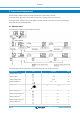
3. Remove the grey cover in the front panel of the charger, enabling access to the terminals.
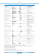
4. Connect battery cables to the charger: plus (red) to “+BAT1”;
minus (black) to “-BAT”
5. Connect battery cables to the battery: plus (red) to positive pole,
minus (black) to negative pole.
6. Connect the mains supply.
2.2.2. Main battery disconnection sequence
When disconnecting the battery cables, be very careful not to accidentally short circuit the battery.
1. Disconnect the mains supply.
2. Disconnect battery cables from the battery.
3. Remove the grey cover in the front panel of the charger, enabling access to the terminals.
4. Disconnect the battery-cables from the charger.
5. Disconnect all other cables like temperature sensor and/or voltage sensor used with this particular battery.
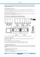
2.3. Connecting the starter battery
The Skylla-IP65 is NOT protected against reverse polarity of the starter battery. ("+" connected to "-" and "-"
connected to "+").
Follow the installation procedure. The warranty expires when the Skylla-IP65 becomes defective due to
reverse polarity.
Disconnect the mains supply before making or breaking connections to the main battery.
The starter battery has to be connected using wire of at least 1.5 mm2 (max. 6 mm2 ).
Connect the positive (+) battery-pole to the "Starter battery plus" connector, see Figure 1.
The negative pole of the starter battery has to be connected to the “-BAT” connection of the charger.
The starter battery can draw current from the battery connected to the main battery terminals in case the
voltage of the starter battery is lower than the voltage main battery. However, the main battery cannot draw
current from the starter battery even when the starter battery is fully charged and the main battery is at
minimum charge level.
2.4. VE.Can connection
The two VE.Can connectors provide access for parallel synchronised parallel operation and remote control.
2.4.1. Synchronised parallel operation
Several charge controllers can be synchronized with the CAN interface to a maximum of 10 chargers. This is achieved by simply
interconnecting the chargers with RJ45 UTP cables (bus terminators needed.
The paralleled charge controllers must have identical settings (e.g. charge algorithm). The CAN communication ensures that the
controllers will switch simultaneously from one charge state to another (from bulk charge to absorption for example).The output
Skylla-IP65
Page 3 Installation and wiring