
Product Manual


current of one charger may differ from another charger although connected in parallel.In case of using remote sensors (voltage
and/or temperature), the remote sensor needs to be connected to one of the parallel operating chargers. All other chargers will
share the information via the CAN interface. In case of synchronised parallel operation, the network icon will blink every 3
seconds on all paralleled units.
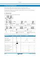
2.4.2. Input/shore current limit
The AC input current limit of each charger is set to 10,5 A max and can be adjusted with a CCGX device, NMEA 2000 or a
Skylla-i-control GX remote panel. See https://www.victronenergy.com/panel-systems-remote-monitoring/skylla-i-control-gx
The input power of one charger will never be more than 1050 W. This means that at 100V AC in the input current is max 10,5 A,
and at 230V AC the maximum input current is 4,5 A.
The input current limit of a parallel charger group can be set with a CCGX device or with a Skylla-i-control GX remote panel. The
current limit as shown on the device is the shore current of the group.
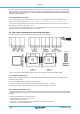
2.5. User relay, external sense and remote shut down
The wiring of these signals must be done with the mains disconnected from the charger.
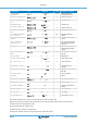
Figure 1 Connectors for external voltage/temperature sensing, Rem. Shut down, VE.Can bus and Starter battery.
2.5.1. External voltage sense
External voltage sensing may be used when accurate battery voltage sensing is important, such as high charging currents in
combination with long cables.
To connect the external voltage sensing option, proceed as follows:
• connect a red wire (0.75 mm2 ) between the positive battery pole and connector "+ Volt. sense"
• connect a black wire (0.75 mm2 ) between the negative battery pole and connector "- Volt. sense”
2.5.2. External temperature sense
The external temperature sensor, supplied with the charger, can be connected to these terminals in order to perform temperature
compensated charging of the battery. The sensor is electrically isolated and must be connected to the positive or negative pole of
the battery.
To connect the temperature sensor, proceed as follows:
• connect the red wire to connector "+ Temp. sense"
• connect the black wire to connector "
• Temp. sense" - mount the temperature sensor on the positive or negative pole of the battery
• check in the menu for the actual temperature
Skylla-IP65
Page 4 Installation and wiring