
Product Manual

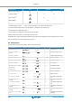
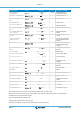

Displayed info Icons Segments Units
Battery charge current out 3
*2
3 60.0
A
Warning message
*3 *4
1 nF 65
Error message
*3 *4
Err 2
BMS operation
*3
BMS
*1
A valid temperature is shown. “ --- “ means no sensor information or “Err” means invalid sensor data.
*2
The output channel number is shown in the first segment; only visible in a three output model.
*3
These items are only visible when relevant.
*4
After a short delay a scrolling text is shown with the error description.
With the up/down keys the user can scroll through the monitor menu.
Holding either up or down for three seconds will start the auto scrolling mode: all Monitor menu items will be shown for 5 seconds.
The auto scroll mode can be exit by pressing up or down once.
3.2. Setup menu
The setup menu can be entered by pressing “SETUP” during three seconds.
Scrolling text Icons Segments Units Function or parameter
01 POWER ON OFF
On,OFF
On/off switch
02 MAXIMUM CHARGE
CURRENT
1.0-60.0
A Maximum charge current
03 SYSTEM VOLTAGE
12
V System voltage (read-only)
04 CHARGE ALGORITHM
1, 2-9
Type Charge algorithm
05 ABSORPTION VOLTAGE
8.0-14.4-15.9
V Absorption voltage
06 FLOAT VOLTAGE
8.0-14.4-15.9
V Float voltage
08 EQUALIZATION VOLTAGE
8.0-15.915.9
V Equalization voltage
09 AUTOMATIC
EQUALIZATION
OFF, AUTO
Automatic equalization
10 MANUAL EQUALIZATION
START
Manual equalization
11 RELAY MODE
rel. 08
Relay Function
12 RELAY LOW VOLTAGE
Lb8.0-11.6-17.4
V Low battery voltage alarm
set
13 RELAY CLEAR LOW
VOLTAGE
Lbc8.0-12.0-17.4
V Low battery voltage alarm
clear
14 RELAY HIGH VOLTAGE
Hb8.0-17.1-17.4
V High battery voltage alarm
set
15 RELAY CLEAR HIGH
VOLTAGE
Hb8.0-16.7-17.4
V High battery voltage alarm
clear
16 RELAY HIGH PANEL
VOLTAGE
U 1.0-150.0
V High panel voltage alarm
set
18 RELAY MINIMUM CLOSED
TIME
?? 0-500
Relay minimum closed time
(minutes)
Skylla-IP65
Page 7 Control and Adjustment