ClearView AV Analyzers System Guide
Table of Contents ClearView AV ........................................................................................................................................ 1 Analyzers .............................................................................................................................................. 1 System Guide ....................................................................................................................................... 1 ClearView AV Analyzer Systems ......
Example 1 .............................................................................................................................. 39 Example 2 .............................................................................................................................. 41 Example 3 .............................................................................................................................. 42 Command Line interface .....................................................................
HotKeys Pane ........................................................................................................................ 84 ClearView Hardware Configurations .............................................................................................. 89 Hardware Modules ................................................................................................................................ 89 CV-SDI-IO-4K ................................................................................
ClearView AV Analyzer Systems Video Clarity created ClearView AV Analyzer Systems (ClearView) to provide video researchers, codec developers, hardware designers, TV Network operators and QA/QC engineers with the unique ability to play, view, record, and objectively analyze audio and video. ClearView allows the capture of video content from virtually any source -- file, SDI, HD-SDI, DVI, HDMI, Component, Composite, S-Video and IP.
Hardware Quick Start Guide ClearView Analyzers comes in three models. The systems are depicted below. Each system is geared to help in a certain segment of the market, while each system runs the core software to maintain compatibility throughout the family. Only a keyboard, mouse, power cable, display and the appropriate input/outputs need to be connected. Figure 1: Product Family -The ClearView Extreme (left) has several product options.
Software Quick Start Guide Double-click on the ClearView icon on the desktop. The following screen will launch. Figure 2: Initial Screen You have several options when starting to use ClearView. If you do not have any video sequences loaded, then you must load one or more: You can import a file. You can capture/record from hardware I/O: o HD-SDI, SDI, HDMI or ClearView I/O channel Now you can Play one (1) video sequence at any rate, change the color parameters, etc.
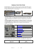
You can click on any hyperlinked box to review the actions needed unless the box is double-lined. In the double outlined box, this is an informative result.
Operations The ClearView GUI screen consists of a number of panes dedicated to specific functions. In the GUI, these panes appear generally in the order of use from top left to bottom right during a typical video quality analysis session. Figure 7: ClearView GUI ClearView allows full control over all of the engineering parameters, which can be selected in any order. (The preferred sequence is shown under "Software Quick Start Guide”.
Choose a Video Output The Video Output controls ClearView’s uncompressed video format to be displayed on external monitors, and also affects the input format during record. Figure 8: Video Output Device Module SD, HD or 4K Note: For 4K format playback and output interface configuration requirements, see hardware module section CV-SDI-IO-4K. Table 2: Video Output Pane Descriptions Output Device The list of Output Devices depends on the optional ClearView Output Modules installed.
Figure 9: Analog Output Device Module SD, HD, 2K The No Output Device uses ClearView's desktop DVI-DL/VGA output to display the video sequences. The Broadcast Output Device uses the HD-SDI, SDI, and Component, S-Video, or Composite output. In addition it also includes 4 stereo channels of AES-EBU on XLR and eight (8) mono channels in embedded SDI (2 in/ 2 out while simultaneously playing and recording). VANC data can be captured and played. VANC acts like a bigger raster size.
Figure 10: Memory/Disk The image format must be chosen next. This item is shown in the Memory-Disk Pane.
Choose a Library The Memory-Disk Pane displays the Memory and Disk properties, allows the selection of image format, and lets the user control the library file system. A library acts like a Windows directory, with a few differences. Similarities: Much like Windows directories, you should organize your video sequences together in a meaningful way. For example, all of the 1080i, 59.94, 8-bit video sequences could be placed in a folder with a useful name about the format, like “1080i_60Hz_8bit”.
Table 4: Library Manager Descriptions New OK Creates a new library. Create a directory using the standard Windows using the New folder Icon Open the directory Choose the sequences file location and select Save. This allows ClearView to recognize a library imported from outside ClearView. For example: restoring a library from tape backup or copying a library from another ClearView system. ClearView needs to reference the sequences file in each library.
Import a File There are two ways to import files: 1) File Import tool pane in the left center of the ClearView GUI. 2) ClearView’s “File Importer.exe” ClearView File Importer The ClearView File Importer.exe is powerful video and audio decoding tool built to provide users the added benefit of several content processing features.
In the case where a (*.ts) transport stream is MPTS, the file contains multiple programs, source information will be updated with corresponding input, according to the selected Hexadecimal PID (Program ID).
ClearView Dependencies Library Libraries are the maintenance folders, used in File Importer and ClearView applications. File Importer destination folder may be used as ClearView input source. Basically, Libraries may be considered as shared locations for File Importer and ClearView. ClearView Library folder specification Libraries have an index file which catalogs information about the video sequences.
Figure 13: ClearView application 1. Click on ‘Library’ folder of ‘Memory/Disk’ section: Figure 14: Memory/Disk section of ClearView 2. Click ‘New’ button in the ‘ClearView Library Manager’ to create new Library. Using the Windows Explorer, navigate to the folder that will be used as the destination for File Importer output, for example ‘H:\1080i50 YCbCr 8bit\’ path. Rev. 8.1.
Figure 15: ClearView Library Manager The ClearView system has no restrictions on the number of libraries that may be created. All new Libraries will be accessible in the ‘Library’ drop down list of Output Sequence section in File Importer. Audio Root Usage Decoded Video and Audio files are stored in a specified destination, based on the ‘Use Audio Root’ option in ‘Config’ screen.
Figure 18: New Format definition 1. 2. 3. 4. Launch ClearView application. Expand ‘Video Format’ drop down list of ‘Video Output’ section. Click on ‘’ in the bottom of the expandable list. In the ‘Custom Resolution’ displayed dialog specify the following: Width (Pixels) – Horizontal amount of pixels Height (Pixels) – Vertical amount of pixels Refresh Rate (Hertz) – Frames per second Figure 19: Custom Resolutions’ dialog 5. Click ‘OK’ button to save custom resolution.
Decoded Files: (with no extension) – Decoded Video raw data .aud – Decoded Audio raw data, may be stored either in Output Library folder, configured in File Importer application, or in a custom location, according to ‘Use Audio Root’ option in the ClearView application .grf - Stored graph that performs decoding. .cvo - This text file contains just the name of the sequence for overlay.
Figure 20: File Importer Graphical User Interface Import File In order to start working with File Importer application it is required to import a video file, which will be decoded according to the output options specified. Figure 21: Source file path Files may be imported the following way in to the File Importer application: Drag and drop – select media file you would like to use for decoding and drag it in to the File Importer screen. Once dragged, release the selected file.
Table 5: File Importer File Types Extension .264, .h4v .264, .h4v .afreq .tpeak .avi .cin .cvp .did .dif .dmos .dps .dpx .gen .icb .jpg .jnd .js .lkfs .mpg. mpeg, .vob, .m1v, .m2v, .m2p, .m2t, .mpv .mpg, .mpeg, .m1v .m4v, .dat .mov .mp4 .omf, .omfi .peaq .pbm .pcx .pgm .pic, .pct .pnm .ppm .psd .psnr .ras .rgb .rgba .rtv .sgi .spatial .sun .temporal .tga .tiff .vda .vst .xmb, .xpm .yuv .yuv10 Rev. 8.1.1 File MPEG-4/AVC, H.264 video file MPEG-4/AVC, H.
After the file is imported in to the application, File Importer populates all the required information and sets default adjustment configuration for Source Modification and Output Sequence sections. Custom Filters File Importer has the ability to allow the user to use different decoders than the ones provided for audio and video. This is done through creating/modifying a file named CustomFiltersList.xml that needs to be place in the File Importer directory.
Figure 22:The GUID is Displayed in the Filter List Once the file is saved to the correct location and the next time File Importer is opened, the new decoder will appear. Below is how the audio decoder shown in the above xml file would appear in File Importer. Figure 23: Audio Decoder drop-down list MPTS Program Select File Importer allows video files with more than one stream to be imported and used for decoding purposes.
In case loaded file offers single program transport stream – the list will contain only default ‘0’ value. In order to navigate through available program streams, expand ‘MPTS Program Select’ drop-down list and select desired Program ID (PID) Hexadecimal value for decoding. Figure 24: MPTS Program select drop-down list After the MPTS Program is selected, File Importer will reload and populate Source File Properties section, since various streams may contain different source information.
Figure 25: CS Coefficient selection Source Crop File Importer source cropping functionality provides the ability to define the area of the imported video to be used in decoding process. Source cropping is defined in the ‘Source Modification’ section - ‘Source Crop’ adjustable fields. The following options are available: L (Left) R (Right) T (Top) B (Bottom) Source cropping definition is done in pixels. Adjustable fields allow only numeric input.
Figure 26: Source Cropping – 50 pixels from each side Sequence name ‘Sequence Name’ field identifies the file name that will be used for the decoding output. The field allows alphanumerical input with special characters. After the decoding process is completed with certain ‘Sequence Name’ value specified, the following files will be created with provided input: (with no extension) – Decoded Video raw data; .aud – Decoded Audio raw data; .
Library As it was already stated before, ‘Library’ identifies the location of the output files after the decoding process is completed. ‘Library’ drop-down list contains all available Libraries, created in ClearView application. Note: Please refer to the 4.1.1 section for the information on how to define new Libraries in ClearView application. In order to select certain ‘Library’ it is needed to expand corresponding drop-down list and click on the desired path.
Video Format Video Format selection identifies resolution and frame rate in which the video will be decoded. According to ‘Output Module’ selected, ‘Video Format’ may hold two different sets of output resolutions. Table 6: Output Format No Video Output Module 720 x 486 30 Hz; 720 x 526 25 Hz; 1280 x 720 25 Hz; 1280 x 720 30 Hz; 1280 x 720 50 Hz; 1280 x 720 60 Hz; 1920 x 1080 25 Hz; 1920 x 1080 30 Hz; 1920 x 1080 50 Hz; 1920 x 1080 60 Hz **Any Custom Format Output Format Broadcast Output Module 525 59.
Figure 29: Available Video Format options for Broadcast Output Module Image Format File Importer allows applying certain Image Format to be used in output video sequence. Offered ‘Image Formats’ are: • Y’CbCr 8 bpc – Broadcast I/O format • Y’CbCr 10 bpc – Broadcast I/O format • ARGB 8 bpc – DVI I/O format Figure 30: Image Format selection Rev. 8.1.
In order to select the desired Image Format, please expand corresponding drop-down list and click on the value you would like to be applied for the decoded video. Frame Range ‘Frame Range’ adjustable fields identify the range of the imported video file to be used for the decoding process. The following fields are available for ‘Frame Range’ adjusting: • F (First) – Number of the first frame to be used; • L (Last) – Number of the last frame to be used in video decoding process.
Figure 32: Scaling source of 1920x1080 to 1280x720 By default, the fields are updated with the resolution of the imported video file. Note: Scaling resolution may not be greater than two times of the selected ‘Video Format’, meaning that for 720p output resolution, maximum scaling definition is 1560x1440 pixels. Canvas Location ‘Canvas Location’ identifies the location of the video to be placed on the screen, in case black padding is displayed, or the video resolution exceeds ‘Video Format’ specified.
Figure 33: Canvas Location set as ‘Top Left’ Note: ‘Use Custom Shift Values’ option allows defining user-specified shifting. This functionality is described in 6.1.16 section. Custom Shift By default, ‘Custom Shift’ adjustable fields are disabled for editing and display the values of current video positioning on the screen according to output Video Format specified. In order to enable ‘Custom Shift’ it is required to select ‘Use Custom Shift Values’ in the ‘Canvas Location’ drop-down list.
The value in Y field that defines per-pixel shifting from bottom left to bottom right corner. Figure 34: Custom Shifting (X:320, Y:140 ) Truncate to Legal Broadcast Values ‘Truncate to Legal Broadcast Values’ functionality is used in YUV Luma only. Pixel intensity values for the Y Component that are above or below the following values should be truncated to only values within this range. In order to apply truncating, please check the corresponding checkbox before decoding the video. Rev. 8.1.
Figure 35: Truncate to legal broadcast values’ checkbox checked Use Audio File Importer provides the ability of video decoding with up-to 8 audio channels. Once the video file is imported, application loads and automatically selects all available audio channels. Unavailable audio channels will be displayed as grayed out checkboxes.
Sliding through the source video file immediately displays the selected input frame in the Input Video Preview screen and maintained (adjusted) frame in the Output Video Preview screen. Figure 37: Per-Frame Slider placed on 117th frame In order to use per-frame sliding, you may use arrows on the left and right sides of the slider, or put the focus anywhere on the sliding scale. Additionally, with the focus put on the sliding scale, it is possible to navigate using keyboard arrows.
Figure 38: Import in progress After the ‘Import’ has completed, ‘Progress’ bar will turn to solid-green and ‘Status’ bar will hold ‘Import file complete’ message. Rev. 8.1.
Figure 39: Import complete To start maintenance of the next video file, it is needed to import it from the beginning. GUI Examples Example 1 Source: Interlaced file; MPTS program support; Video Format: 704x280 29.97 Hz Required maintenance for output file: MPTS Program – 108; De-Interlace; Change Rate; CS Coefficient change – SMPTE 240M Library: ‘C:\Program Files\Video Clarity\FileImporter\Library\’ Video Format – 720p 60.00 Hz; Canvas Location – Top Right Rev. 8.1.
File Importer Settings: 1. 2. 3. 4. 5. 6. 7. 8. Import Source video file Expand ‘MPTS Program Select’ list and select 108 value Select SMPTE 240M as ‘CS Coefficient’. Select ‘Library’ path: ‘G:|’ Select ‘Broadcast Output Module’ as ‘Output Module’; Expand ‘Video Format’ drop-down list and select 720p 60.00 Hz; Set Top Right value in the ‘Canvas Location’ drop-down list. Click on ‘Import’ button.
Example 2 Source: Interlaced file; MPTS program support; Video Format: 704x280 29.97Hz Required maintenance for output file: MPTS Program – 105; Change Rate; Sequence Name: 105_Import; Library: ‘C:\Program Files\Video Clarity\FileImporter\Library\’ Video Format – 1080i 60.00 Hz; Scale Source to – 1920x1080; Canvas Location – Center. File Importer Settings: 1. Import Source video file; 2. Expand ‘MPTS Program Select’ list and select 105 value; 3. Define 105_Import as ‘Sequence Name’; 4.
Example 3 Source: Progressive file; Video Format: 1280x720 22.21 Hz Required maintenance for output file: Change Rate; Source Crop: L:50; R:50; T:20; B:20; Library: ‘C:\Program Files\Video Clarity\FileImporter\Library\’ Output Module – No Video Output Module; Video Format – 1920x180 25 Hz; Image Format – YCbCr 10 bpc; Frame Range – F:20; L:250 Custom Shift – X:140; Y:200; Truncate to legal broadcast values – checked; Use Audio: A1 File Importer Settings: 1.
Figure 43: Example 3 File Importer Settings Command Line interface ClearView File Importer provides the ability for the video to be decoded using a Command Line input. All settings, available in Graphical User Interface mode are also configurable with specific input commands using the Command Line Interface. It is possible to adjust the Source Modification and Output Sequence options for the videos and decode the files behind the scene.
Table 7: Command Line Input Commands Command Description Supported value / type "fp" Input file path File path "pid" Program ID Number "de" De-interlace "0" / "1" "chr" Change frame rate "0" / "1" "pd" 3:2 Pulldown Not implemented "cs" CS Coefficients - "BT709 1125" - "SMPTE 240M" "cl" Crop left value Number "cr" Crop right value Number "ct" Crop top value Number "cb" Crop bottom value Number "sn" Sequence name Name "lp" library path Folder path "om" Output Module - "No Video Output Module" - "Broadcast Out
"tr" "a1" "a2" "a3" "a4" "a5" "a6" "a7" "a8" "ualp" "alp" "dbg" “adec” “vdec” “isn” Truncate to legal broadcast values Use audio 1 Use audio 2 Use audio 3 Use audio 4 Use audio 5 Use audio 6 Use audio 7 Use audio 8 Use audio library path Audio library path Debug mode Audio decoder name to be used Video decoder name to be used Select name of sequence when importing off of a ClearView sequence file "0" / "1" "0" "0" / "1" "0" / "1" "0" / "1" "0" / "1" "0" / "1" "0" / "1" "0" / "1" "0" / "1" "0" / "1" Fold
Example 2 Source: Interlaced file; MPTS program support; Video Format: 704x280 29.97Hz Required maintenance for output file: MPTS Program – 105; Change Rate; Sequence Name: 105_Import; Library: ‘C:\Program Files\Video Clarity\FileImporter\Library\’ Video Format – 1080i 60.00 Hz; Scale Source to – 1920x1080; Canvas Location – Center. Command Line input: -fp "F:\\video\\Video005.
ClearView File Importer Problem Solving This section reflects potential issues that may be faced during the ClearView File Importer application’s execution and possible resolution. # 1. Issue MPTS-supporting files take more time to be imported, than other file formats. 2. 3. 4. Black line appears on the Output Video Preview screen in case ‘YCbCr 10 bpc’ image format is applied to ‘720p’ video format. Some files do not support seeking. Video Import has failed. 5. Output audio files are not created.
WMA WAV AIFF MP3 Note: ClearView deciphers the file based on the file extension. You must use the correct extension. ClearView supports the extensions listed below. Table 8: Supported File Extensions (also supported by ClearView File Importer) Extension File .264, .h4v MPEG-4/AVC, H.264 video file .aac Advanced Audio Coding, .afreq Video Clarity aFreq parameters .tpeak Video Clarity aPeak(TruePeak) parameters .aiff Audio interchange file format, .amr Adaptive multi-rate audio codec, .
Extension .sun .temporal .tga .tiff .vda .vst .wav .wma .xmb, .xpm .yuv .
To Disk Fld Flip First Last Load Abort text. When checked, import to the File System. When unchecked, import to Memory. Note: Audio is not currently written to Memory. Reverse (flip) the top and bottom fields during import. The first frame to be loaded from a sequence of files. You can use this to import part of the video sequence. The last frame to be loaded from a sequence of files. You can use this to import part of the video sequence. Initiates the load process.
Import Objective Metric Log File The objective metric log file includes: Objective Metrics – AFREQ, APEAK, LKFS, DMOS, JND, PEAQ, PSNR, SPATIAL, or TEMPORAL Clip Alignment Parameters Image and Video formats Video Sequence names and Library locations Default parameters used when calculating the metrics If the library, video sequences, etc. exist, then the video sequences will be loaded, the clip alignment will be set, and the objective metrics will be restored (no need to recalculate).
Figure 45: Choose the first of a sequence of BMP files Note: the File Import pane will display information about the file or files that have been selected. In this example, .bmp files are imported. However, this behavior is the same for any file type. Load Headerless files File Importer needs to know more about these files to load them correctly. Header files have been defined to help ClearView to understand this data the description of the file is defined in File Import Descriptions below .
%Image Size %Number of Fields per Image %Number of Images %Frames per second %Header Offset %Video Offset %Video Alignment %Video Name %Audio Name DPXABGR - DPX 10 bit ABGR, big endian, padded RGBA – 32 Bit Interleaved RGB (TIFF) ARGB – 32 Bit Interleaved RGB (Mac) BGRA – 32 Bit Interleaved RGB (Windows BMP/TGA) BGR – 24 Bit Interleaved RGB (Windows BMP/TGA) TIFF24 - 24 Bit Interleaved RGB TIFF ordering TIFF32 - 32 Bit TIFF (same as RGBA) PRGB - 8 bit x 3 Planar RGB PRGBA - 8 bit x 4 Planar RGBA PBGR - 8
%Timecode %Userbits %Start Frame This is the time code for the first video frame. It will run continuously from here. Given as hrs:min:sec:frames (Optional) A query of the value of the user bits will return this value for all frames. (Optional; ClearView does not currently extract the user bits.) This indicates the frame number of the first frame in the video file. It is normally 0, unless you are using some type of circular file as input.
Use Metric Adjust Sequence Frames Abort on Drop Status Drop Out enable Preview Record Snapshot Stop mode. Checking this box will start the process of re-recording the 2 video sequences associated with Viewport A and Viewport B. The video sequences are rerecorded after apply spatial alignment, normalization, and windowing. Note 1: for spatial alignment, the alignment must be an even number to avoid color shifts in Y’CbCr space and/or flipped fields in interlaced modes.
Record ClearView Output The ClearView Output tab allows the user to record the video sequences currently playing in Viewport A and Viewport B. 3 reasons exist to do this Record split screen video sequences as a single video sequence so that they can be exported later for offline analysis/viewing Record a portion of the video sequence (or split screen video sequences) as a single video sequence so that they can be exported later for offline analysis/viewing.
Record 1 Broadcast Input In Broadcast input mode, make sure the source is connected before previewing and ClearView will auto senses the video format. To make sure that it has selected the correct format, select the Config button which is displayed below.
The Broadcast tab – Record Mode Single Input records the video sequence as sensed on the HDMI or SDI input. The SDI can be either SDI Input #1 or SDI Input #2 and the HDMI can only be set as HDMI Input (as set by Config). ClearView Extreme-4K: 1 Broadcast Input 4K ClearView Extreme can record up to 25Hz when using “Broadcast Output Module 1” or “Broadcast Output Module 2”, but can record in up to 60Hz when using “Broadcast Output Module 1 & 2”. The image below shows how the signals will appear.
Figure 50: Record 2 Broadcast Inputs Record Broadcast Input While Playing The Broadcast tab – Record Mode Input/Output records the video sequences as sensed on the Input selected. The outputs on the broadcast board will play out the video that is currently in the viewport. This allows the user to play through SDI and encode the signal to be recorded into the machine. Once the preview has started and displays the video, the recording can start by pressing the record button.
Record 1 IP Input In IP input mode, a configuration option will pop up as shown below. The video format needs to be set in the main ClearView window under Video Output. Figure 52: Record 1 IP Input Figure 53: Configure IP Input Rev. 8.1.
Table 16: Configure IP Input Description Protocol Chose among the three protocols of the incoming stream: RTP UDP RTSP Address The address that the stream is located Port The port number to find the stream Stream Name When using RTSP Protocol, specify the stream name Transport Type The transport type of the stream: Mpeg2 TS AVP/UDP Unicast Mpeg2 TS AVP/UDP Multicast Mpeg2 TS AVP/TCP Unicast Unicast RTP over UDP Multicast RTP over UDP Multicast Raw over UDP Interleaving Unicast Raw over
Record 2 IP Inputs The IP Input tab – Record Mode Dual Input records the video sequences as sensed on two separate multicast addresses and ports specified from within the configuration menus. Each video can go to a different library and both must have different sequence names. Figure 51: Record 2 IP Input Record IP While Playing The IP Input tab – Record Mode Input/Output records the video sequences as sensed by the multicast address and port.
Figure 52: Record IP While Playing Select Thumbnail to Play or Export The Sequence Manager pane displays thumbnails (or details) of the video sequences currently loaded into the current ClearView library. Two video sequences can be loaded at any time. Each video sequence is assigned a Viewport. After a file is imported or a video sequence is recorded via hardware inputs, the first video sequence is mapped to Viewport A. The second sequence loaded is mapped to Viewport B.
In the other modes, moving the video sequence to the left side of the Viewport (or top in Horizontal Split) will assigned it to Viewport A. Moving the video sequence to the right side of the Viewport (or bottom in Horizontal Split) will assign it to Viewport B. As the following figure shows, right-clicking on a sequence thumbnail allows you to change the Viewport assignment, to unload video sequences from memory or disk, to see the details, or to export the video sequence to a file.
Figure 55: Sequence Manager Export Controls Table 18: Sequence Manager Export Descriptions Sequence Selected Sequence, Image Type, First Frame, Last Frame are informational Properties only. They cannot be changed File Type The video sequence can be exported as a BMP, RAW, MOV, AIFF or AVI file All Checking this box exports all of the frames. Unchecking this box allows you to set the first and last frame to output.
Select a View Mode The View Mode pane allows you to select the current viewing mode. Figure 56: View Mode Controls Table 19: View Mode Descriptions A Only Display only Viewport A; i.e., the video sequences associated with A. (Note: Viewport B may be playing). B Only Display only Viewport B. (Note: Viewport A may be playing). Side-by-Side Display Viewports A and B side –by side. SeamlessDisplay Viewports A and B flowing as if they were 1 video sequence.
In a typical operation, the original uncompressed clip (the original source file) and the corresponding decompressed clip (a compressed version of the source file, decompressed by ClearView) are shown as successive thumbnails. Note, however, that there is no restriction on the assignment of clips to Viewports. You are free to assign any still or clip to either Viewport, whether that makes any sense or not.
Select Objective Measurements The Objective Measurement Graph pane displays the graph of the JND, PSNR, PSNR No Ref, Spatial, or Temporal over time. The actual value, minimum, maximum and average values are displayed in the Objective Metric Controls pane. Examples, using the various objective measurements are on our website under www.videoclarity.com/WhitePapers.html.
LKFS LKFS, Loudness K-weighted relative to Full Scale, can be run by checking the box within the a-Peak tab. LKFS is a no-reference metric. This metrics gives a measurement that will take the peak loudness (amplitude) over a variable time scale over all audio channels, and respond with one value for all channels that corresponds to that one second time period. The values that are returned are based on a logarithmic scale with 0 being the maximum value and -60 being close to silence.
Spatial Spatial measures the activity within a video sequence. Spatial is a no-reference metric. Large values indicate a substantial change within an image - for example: panning stadium crowds would generate a large Spatial Index. A solid color would produce a low Spatial Index. For more information about the Spatial metric, please refer to ITU-T P.910 (a link is on our website at www.videoclarity.com/WhitePapers.html).
maximum, and average Objective Metrics are displayed along with the graph. Using the shuttle bar (slide bar), the user can display any frame to visually assess the 2 video sequences. Note: The frame is associated with the right side of the slide bar. Pixel Values To display individual pixel values press the right mouse button. Note: the left mouse button will still control panning. Scrolling to any X,Y location will show the pixel values for the same location for both video sequences.
Figure 64: Pixel Value Controls Figure 65: DMOS Objective Metric Figure 66: aFreq Objective Metric Figure 67: Spatial Objective Metric Rev. 8.1.
Figure 68: Temporal Objective Metric Figure 69: PEAQ Objective Metric Figure 70: a-Peak Objective Metric Rev. 8.1.
Table 21: Objective Metrics Description Note: Moving among the Objective Metrics does not turn on or off the metric calculations. This simply displays the collect data. DMOS This tab selects the DMOS Metric settings Note 1: DMOS takes a considerable amount of time so we do not allow moving to another pane while this calculation is processing. JND Note 2: Chroma now enabled for DMOS.
Note 2: Choose channel you want to run aPeak metric. Multiple channels may be chosen to run metric test simultaneously. Graph shows metric data in graph window. Button below log creates log file. Note 3:To run LKFS instead of aPeak click the LKFS box on. This will run on all audio channels whether they are checked or not. The resulting log file will have .LKFS as the extension.
Graph Log average. Display the Y/G, Cb/B, or Cr/R values over time on the Objective Metric Graph. If the data has not been calculated, then pushing this button will play the video sequences, calculate the Objective Metrics, and display them. Note 1: Y/G data will be printed in Green. Cb/B data will be printed in Blue. Cr/R data will be printed in Red. Note 2: In the upper, right corner, the graph will display A for both PEAQ and AFREQ, D for DMOS, J for JND, P for PSNR, S for SPATIAL, and T for TEMPORAL.
Figure 71: A Minus B Controls Table 23: A Minus B Descriptions A-B Use Diff Checking this box performs a |A-B| > Threshold on either the Chroma or Y Threshold pixels Unchecking this box, performs an A-B > 0 on all pixel values If true, it displays the difference.
Normalize Y/G, Cb/B, Cr/R X, Y, W, H Checking this box performs a Luminance Intensity and Chrominance Hue calculation. The current video frame in Viewport B is compared to the current frame in Viewport A. The results are show in Y/G, Cb/B, Cr/R. Note: The video sequence is not adjusted. This offset only applies to the objective metrics. Note2: The offset is a linear offset per frame and is used to adjust the brightness or color hue.
Unchecking this allows Viewport A and B to operate at different rates. Save alignment changes Temporal Align Note: Viewport A has a video sequence originally compressed at 3fps. Viewport B has the uncompressed video sequence. To play these at the same rate, set Viewport A’s Speed to 0.1 and Viewport B’s Speed to 1.0, and Uncheck this box. Checking this saves the changes that you have made to first and last.
Figure 74: Color Space Controls Table 26: Color Space Description Y/ G Check displays the Y or G. Uncheck turns this color space off Cr / R Check displays the Cr or R. Uncheck turns this color space off Cb / B Check displays the Cb or B. Uncheck turns this color space off. Y’CbCr is in Broadcast space; RGB is in Broadcast RGBA or DVI ARGB space. Overlay This puts the overlay text over the video sequence. The overlay is a text file which has the same name as the sequence name with a .cvo extension.
Preview Update Pane The Preview Update pane (at the top right corner of the GUI screen) controls the refresh of the preview displayed in the center of the ClearView GUI. Note 1: This preview display is never updated faster than 30Hz so you should never rely on it as your only output. Note 2: The preview is also decimated both horizontally and vertically. You cannot trust the image quality in this window.
modes is that the math turns into B-A. Multiple Outputs Note: This gets very confusing. It is better to simply reload the sequences. Checking this sends Viewport A to one SDI output and Viewport B to the other. Note 1: This mode works only with the CV-SDI-IO-DL module or with the ClearView Extreme with 2 Broadcast I/O modules Note2: This only works if the View mode is A-only or B-only. Zoom Pane The Zoom Pane allows integer-based, pixel replication zoom in both X and Y.
Play Mode Pane The Play Mode pane controls whether the clip is played 1x, forever in a loop, or forward then backward repeatedly. The Alternate A/B plays sequence A, then sequence B repeatedly. Figure 79: Play Mode Controls Field/Frame Mode Pane The Field/Frame Mode pane allows various options for viewing fields and frames. This is mainly used for interlaced material. These options are independent for Viewport A and Viewport B.
Blacken Duplicate Pixels Note: Blacken Duplicate Pixels turns off the other field so F1 only means field 1 when displaying field 1 and black when displaying field 2. F2 only means black when displaying field 1 and field 2 when displaying field 2. This displays black for the field that is being duplicated above. Please read the note sections above. HotKeys Pane The HotKeys pane allows the user to set various parameters and to see some attributes about the system.
Figure 82: Configuration Settings Table 32: Configuration Setting Descriptions Playback Broadcast Playback – Use Reference Source checkbox to choose a reference source for your broadcast boards. These are the default playback parameters for both broadcast and DVI.
It changes where we place the video sequence if the raster size is larger than the video sequence. It changes where we start the video sequences if the raster size is smaller than the video sequences. Objective Metrics Note: The others items in this group should be checked only after talking to Video Clarity customer support. Threshold Failure Overlay – Places the text Failure in an overlay on the video when the threshold is passed.
and 1023 for 10-bit. ANSI suggests using 235 for 8-bit and 940 for 10-bit, which is the setting used if you select this option. PSNR Linear Average – Setting this feature changes the average from a quadratic average to a linear average. Save Spatial Alignment – Setting this feature saves the temporal/spatial alignment with respect to the sequence in Viewport B. So if you change the sequence in Viewport A we will still keep the spatial changes saved.
Figure 83: HotKeys To change a Hotkey (aka keyboard shortcut), place the mouse in the space next to the function and type the keyboard sequence. Please remember that the keyboard sequence must begin with Ctrl or Alt. After changing the Hotkey, press OK. It will be saved for future use. Note: Enable is set off by default so HotKeys are not active. You need to enable them. FPS is the current frame rate. Reset restores ClearView to its state when first entered.
ClearView Hardware Configurations Each ClearView product model has a specific IO configuration based on model configuration and specifications available at the time of purchase. There are several potential IO configurations that have been developed which are supported for the life of your product.
ClearView stores and plays video data as 100% uncompressed 8 or 10-bit 4:2:2 Y'CbCr. Figure 86: Playback Using Reference Config Below are the different configurations of the switches (taken from the Gen10 manual) on the back of the AJA Gen10 which is the supplied sync source for dual 4K board ClearView models. This section does not apply to systems delivered without a sync generator, from May 2014 and beyond. Figure 87: AJA Gen10 Format Table from AJA documentation: Rev. 8.1.
ClearView Extreme-4K: Two Board Input/Output – Pre May 2014 Playing or recording 4K is provided up to 60Hz in by using two CV-SDI-IO-4K modules or “Two Boards”. The Formats displayed in dual board 4K systems are listed in the GUI pulldown as “2x2x1920x1080” to indicate that the quadrants of a 3840X2160 image format are tiled 2x2. Each tile is carried by one 3G HDSDI input or output in a shared configuration between the two interface boards.
ClearView Extreme-4K: Two Board Input/Output – Post May 2014 Playing or recording 4K in a system delivered post May 2014 is provided up to 60Hz rate by using one of the two CV-SDI-IO-4K back panel modules. The Formats displayed in the GUI pulldown as “4x1920x1080”are used. To record video select “Broadcast Module 1” which is the module on the right and to playback video select “Broadcast Input Module 2” which is the module on the left.
2. 4K formats are not supported via analog IO, therefore analog breakout interfaces are only for HD or SD format play and record. 3. In all configurations, one HDMI converter per HDSDI may be used for Quad HDMI monitors or a Quad/HD to HDMI converter for a single HDMI input monitor may be used. 4. Also, the native HDMI mini connector is for output only and supporting up to 3840X2160P @ 30Hz, 4:2:2 in the Post May 2014 model configurations.
3G, HD-SDI, SD-SDI I/O Analog Video Inputs & Outputs 12-bit HD Analog Component I/O 12-bit SD Analog Component/Composite/S-Video I/O Digital Audio Inputs & Outputs 2-ch Balanced XLR AES I/O, 24-bit 48KHz 8-ch SDI Embedded Audio I/O, 20-bit 48KHz 2-ch HDMI Embedded Audio I/O, 20-bit 48KHz Analog Audio Inputs & Outputs 2-ch Balanced XLR Analog Audio I/O, 24-bit 48KHz I/O Format Standard Definition (SD) 525i 59.94 Hz 625i 50 Hz High Definition (HD) 720p: 50Hz, 59.
4:4:4 HD-SDI Dual-Link or dual 4:2:2 HD-SDI, SDI Single-Link Analog Video Output 3 X BNC - Component (Y’Pb'Pr or RGB) 1 X BNC - Composite (Shared with Component BNC connections) 2 X BNC – Y/C composite input (Shared with Component BNC connections) 10-bit D/A Input Formats 525i 59.94 Hz 625i 50 Hz 720p (50, 59.94, 60) Hz 1080i (50, 59.94, 60) Hz 1080psf (23.976, 24) Hz 1080p (23.976, 24, 25, 29.97, 30, 50, 59.94, 60) Hz 2048x1080p (23.98, 24) Hz 2048x1080psf (23.
720p: 50Hz, 59.94Hz, 60Hz 1080i: 50Hz, 59.94Hz, 60Hz 1080psf: 23.98Hz, 24Hz 1080p: 23.98Hz, 24Hz, 25Hz, 29.97Hz, 30Hz CV-SDI-IO-CVD22 Figure 94: CV-SDI-IO-CVD22 Broadcast I/O Module The CV-SDI-IO-CVD22 module records, plays or simultaneous records and plays HD/SD videos. It is capable of 1080p/60Hz record or playback with up to eight channels of embedded audio.
Output Formats (independent from Input) 525i 59.94 Hz 625i 50 Hz 720p (50, 59.94, 60) Hz 1080i (50, 59.94, 60) Hz 1080psf (23.976, 24) Hz 1080p (23.976, 24, 25, 29.97, 30, 50, 59.94, 60) Hz CV-DVI-O Plays 100% uncompressed DVI digital video and VGA analog video. The DVI/VGA Output Module can create custom video raster formats; it is completely programmable to any video with a pixel clock less than 400MHz.
CV-DP/DVI-O Figure 100: CV-DP/DVI-O Broadcast I/O Module. DP Out 1 DP Out 2 DVI-I-D Out The ClearView Display Port Output Module plays 100% uncompressed RGB digital video from Display Port or DVI outputs (or VGA analog video) in Progressive (P) mode. The Display Port Output Module can create custom video raster formats. It is completely programmable for video formats that require a bandwidth of 17.28 Gbps or less.
File Format Import Types Accom YUV CCIR 601 8 Bit ARI Raw Bayer Pattern Avid AVR, DS HD/SD, DV (*.gen) Avid _DNxHD Avid Meridian & Y’CbCr Avid OMFI (*.omf, *.omfi) AVR, JFIF, JPED, Meridian, RGB, Y’CbCr Cineon (CIN) CineWave Digital Negative (.dng) DPIX (DPX) DV Movies (*.dv, *.dif) DVS Direct File Format (*.dvs) DVSD, DV25, DV50, MPEG-I, MJPEG DigiSuite H.261 H.263 HDV Headerless/Raw (*.hdr, *.yuv, *.rgb, *.raw) HiCon SLB32 RFB format (*.slb) Image (gif, jpg, png) Jaleo Direct Format (*.