
Manual

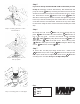


Step 9
Now attach the master support PM-2 to the top plate PMC-S
using the M6 security screws PMC-S , washers PMC-S, and nylon
nuts PMC-S.
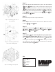
Step 10
Place the washers removed in Step 8 PM-2 on top of the cen-
ter hole in the top plate PMC-S and underneath the center
hole in the master support PM-2. Insert the ¾” screw PM-2
through the washers, master support, and top plate and use the screw
PM-2 to attach the extension support and PM-2. Secure the ¾”
screw using the ¼” – 20 brake screw PM-2. Proceed to Step 15.
Step 9 : Attaching the master sup-
port to the top plate
Step 10: Attaching the extension
support to the top plate
Key:
VIDEO MOUNT PRODUCTS
PM-2
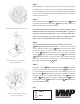
Step 8
The next steps assume you are attaching the PMC-S to an already
mounted PM-2. If the mount is not assembled please f rst follow
the instruction sheet provided with the PM-2 up to the point where
you decide if you are using the ceiling mast or f ush mounting
and skip step 9. Remove the projector from the clamps. Next re-
move the extension support PM-2 by removing the 5/16” screw
PM-2 and nylon nut PM-2. Detach the extension support
PM-1 by fi rst removing the ¼” - 20 brake screw PM-2 and
then removing the ¾” screw PM-2 and washers PM-2.
Step 8 : Removing the extension
support from the master support
PMC-S
1
17
18
19
17 22
20
21
2
7
8
10
21
1
2
20
21
17
22
21