VIA-PRO Security System Manufactured by RSIalarm Document No.
Table of Contents About This Document......................................................................................... 1 Special Installation Requirements................................................................ 1 UL Listed Installations....................................................................................... 1 Basic System Devices ....................................................................................... 1 Household Burglary Alarm System (UL 1023)..................
About This Document This installation manual provides the necessary information for installing, configuring/programming, testing, and troubleshooting RSIalarm™ security systems. This installation manual does not provide mounting information for individual devices compatible with the control panel. This installation manual does not provide complete system operating information. Please refer to the VIA PRO Users Manual. Special installation requirements.
Installation Planning It is recommended that you plan the system configuration and programming by writing it all down. This will help speed programming by having all the information in one place. Use pages 2 - 3 to record all system configuration settings. System Information Tables Area Names Areas determine how the control panel responds to device assigned to a specific area. Area 1 is always used for all alphanumeric keypads and any entry/exit delay points.
Reporting Format and Central Station Numbers Central station communication and reporting formats, phone numbers, and IP address’s (depending on format choice) must be programmed. There are seven reporting formats to choose from. Each format requires a subscriber (account) number for customer identification at the central monitoring station. Email Alarm Messages The system can send alarm messages and video files to 2 designated email address’s.
Keypad Programming 5 MNO 7 TUV 8 WXYZ m 0 6 ESC NO 9 @ @—use for special text and punctuation entries. YES ESC/NO— backout of a menu or skip to the next one. YES— proceed with the prompted action or accept the displayed entry/setting. 1 space . , ? ! ; : 1 2 A B C 2 3 D E F 3 4 G H I 4 5 J K L 5 6 M N O 6 7 P Q R S 8 T U V 8 9 W X Y Z 0 - + = @ @ $ % / ) 0 7 9 ¥ & 11th press JKL CLR—clear numerical/ text entries.
Installation Planning Phone Line Connections Installation Guidelines It is recommended that you install new systems in the following order: > Run the required system wiring (phone line for RJ31X jack). > Mount the control panel. > Power up control panel and clear memory. > Program alphanumeric keypad into the control panel. > Program system parameters. > Program detectors into the control panel and test them. > Mount detectors. > Exit programming mode. 1.
Installation Sequence Power Up Control Panel and Clear Memory Programming an Alphanumeric Keypad into the Control Panel For new installations, always clear the control panel memory after powering it up for the first time, and before programming any devices or other system information. An alphanumeric keypad must be programmed into the control panel first, in order to perform any on-site programming. 1. Remove the end screws on the control panel to remove its cover and install the batteries.
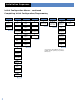
Installation Sequence Initial Configuration Menus The next two pages show the order in which menus appear for the initial programming session (beginning with the Installer Code). After these pages, the manual continues with details of each menu and the data entries required. Installer Code Date & Time Format Code/State Modification 4 -6 Digits Year Surtec/CID Frontel Combined Formats Trans.
Installation Sequence Initial Configuration Menus – continued Completing Initial Configuration /Programming Enter Your I.D. Sending Alarm By Email Voice Transmitter Areas Configuration Exit Delay Entry/Delay Recording Devices End of Configuration Panel Phone Number Indentification Code Voice Notif. NBR 1 Area Name 1 (45 sec), 1 min 2 min (15 sec), 30 sec, 45 sec, 1 min, 2 min Press Init.
Installation Sequence Initial Configuration/Programming Installer Code Lets you program a code that is used for all programming and maintenance functions. The installer code cannot arm/disarm the system. Note: An installer code must be programmed in order to program user access codes. 1. With the display showing INSTALLER CODE: enter the desired code, then press YES. The display shows CONFIRM CODE. 2. Re-enter the code and press YES. The display shows CODE NAME. 3.
Installation Sequence Initial Configuration/Programming For Frontel Format 1. With the display showing FORMAT:, press either arrow button until FRONTEL is displayed, then press YES. 2. With the display showing PHONE PREFIX:, enter the required prefix (such as a 9 with a pause for outside line access) + YES or press ESC/NO if no prefix is required. Note: To program a pause, press the @ button six times for the # sign. Each # entry adds a 2-second pause. 3.
Installation Sequence Initial Configuration/Programming Alarm Code Modification Code/State Modification? [YES = continue, ESC/NO = skip] Tran. State Modification Lets you change the control panel default settings for how and/or whether certain conditions are reported to the central station. There are three possible settings for each state: Lets you change the default alarm reporting code of each system device.
Installation Sequence Initial Configuration/Programming Bypass Activiation Lets you set up the system so operators in Frontel supported central stations can initiate contact with and access the system. 1. With the display showing BYPASS ACTIVATION?, press YES or ESC/NO. Enter Your I.D. Your Phone Number 1. With the display showing PANEL PHONE NUMB:, enter the customer site phone number, then press YES. The display shows NAME OR ADDRESS. 2. Enter the customer name and address, then press YES.
Installation Sequence Initial Configuration/Programming Using The Voice Transmitter Area Configuration Area Name 1 Lets you set up the system for voice reporting to as many as three customer designated phone numbers. The report includes the device, zone, alarm type, time, and date. Lets you name each of the four areas used for identifying the different areas of the installation. Area 1 is predefined from the factory for alphanumeric keypads and any entry/exit delay points.
Installation Sequence Initial Configuration/Programming Recording Equipment Press Init. Butt. On Equipment Camera PIR Motion Detector Lets you program system devices into the control panel memory. 1. Install batteries into all system devices* (refer to the installation instructions). Make sure bases are attached to devices to secure the tamper switches. 2.
Installation Sequence Initial Configuration/Programming Completing Initial Configuration/Programming After the last device is programmed, press ESC/NO. The display shows END OF CONFIGURATION, then changes to CLOSE THE PANEL. STOP! It is important that you first mount all devices, then secure the cover on the control panel. Failure to follow this order of tasks will cause a tamper condition from devices. 1. With the display showing CLOSE THE PANEL, do not press YES. 2.
Changing Settings After Completing Initial Configuration/Programming Changing Settings After Completing Initial Configuration/Programmin Once the control panel cover is secured in place, removing it causes a tamper alarm. Changing settings made during the initial configuration or adding devices now requires setting the system to Access Level 4, using your installer code. Setting the System to Level 4 1. With the display showing [DATE/ TIME], DISARMED LEVEL:3, press the right arrow button once.
Changing Settings Levels 1 , 2 , 3 , 4 Configuration Date/Time Status/Level Display Badge or Code Access Level After Completing Initial Configuration/Programming SEE NEX T PAGE General Parameter Alarm Modes Programmable Site Identification Fully Armed Areas: State: Phone Number Panel Phone NBR: Alarm Special Mode 1 NBR of Rings Before Connect System Armed (1-15) Responding Party List Areas: State: Alarm Special Mode 2 System Disarmed (1-15) Areas: State: Areas and Devices Responding Par
Changing Settings Maintenance Programming Menu Levels 1 , 2 , 3 , 4 Levels 1 , 2 , 3 , 4 Levels 1 , 2 , 3 , 4 Levels 1 , 2 , 3 , 4 Maintenance Events Log Badges Access Codes Programmable Features Modify Date/Time Select Last Events Maintenance Replace Battery Send Log File By Email Badge or Code Alarm Calls Enter A Badge/Code Functional Test Devices Badge/Code Configuration Device Locating Code List Alarm Transmission Videomail Alarm Email Address Audio Test Equipment Modify Name Bad
Changing Settings After Completing Initial Configuration/Programming Access Level — available in Levels 1, 2, 3, and 4 Events Log — available in Levels 2, 3, and 4 This menu shows the current system level and lets you change the level. Increasing the level always requires a valid access code assigned to that level. Lowering the level does not require an access code. This menu lets you view and send via Email, a list of all system activity and events.
Changing Settings After Completing Initial Configuration/Programming 1. With the display showing the current date, time, and LVL:4, press the left arrow button twice. The display shows BADGES ACCESS CODES. 2. Press YES. The display shows BADGE OR CODE. Enter your installer code + YES. The display shows RECORDING A BADGE/CODE. 3. Press YES. The display shows BADGE OR CODE. 4. Enter the desired code + YES. The display shows CONFIRM THE CODE. 5. Re-enter the code + YES. The display shows CODE NAME:. 6.
Changing Settings After Completing Initial Configuration/Programming Creating Schedules Schedules determine when a specific access code can be used to arm and disarm the system. A schedule consists of a day, beginning time, and ending time that the specific access code can be used. Up to five schedules can be programmed for each access code. Make copies of the table at right to fill in the necessary schedule information for each code. Enter this information using the procedure below. 1.
Changing Settings After Completing Initial Configuration/Programming Setting Up Special Arming Modes 1 and 2 Viewing the History/Event Log These undefined special arming modes are used for Special Area arming of your system. You can set up which Areas of your premises are armed in mode 1 & 2 and if an alarm would be silent or audible. An office in the home could be armed/ disarmed independently.
Specifications Electrical Data Physical Data Power requirements: Four 3.