LCD MONITOR USER MANUAL 45M19H 19” TFT LCD Information may change without notice. This document provides technical information for the user. Videology reserves the right to modify the information in this document as necessary. The customer should make sure that they have the most recent manual version. Videology holds no responsibility for any errors that may appear in this document. Videology Imaging Solutions, Inc.
Table Of Contents 1. 2. Warning ........................................................................................................... 3 Precautions ...................................................................................................... 3 2.1. Safety ....................................................................................................... 3 2.2. Installation ................................................................................................ 3 2.3. Cleaning ...
1. Warning TO REDUCE THE RISK OF FIRE OR ELECTRIC SHOCK: DO NOT EXPOSE THIS PRODUCT TO RAIN OR MOISTURE. DO NOT INSERT ANY METALLIC OBJECT THROUGH VENTILATION GRILLS. CAUTION: Explanation of Graphical Symbols The lightning flash with arrowhead symbol, within an equilateral triangle, is intended to alert the user to the presence of non-insulated dangerous voltage within the product's enclosure that may be of sufficient magnitude to constitute a risk of electric shock to persons.
3. Federal Communications Commission (FCC) Statement This Equipment has been tested and found to comply with the limits for a Class B digital device, pursuant to Part 15 of the FCC rules. These limits are designed to provide reasonable protection against harmful interference in a residential installation. This equipment generates, uses and can radiate radio frequency energy and, if not installed and used in accordance with the instructions, may cause harmful interference to radio communications.
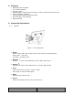
4. Features • • • • • • • • NTSC/PAL Auto Selectable 300 cd/m2 Brightness Remote Control Inputs/Outputs: 2 BNC Composite Video, S-Video, 2CH Audio (RCA) & PC IN Auto Termination 75 Ohms VESA Standard Bracket & Desktop Mount Easy OSD Menu User Interface Wall Mountable 5. Operating Instructions 5.1. Control 1 2 3 4 5 6 Figure 1. 19” LCD Monitor 1. Power Monitor power ON / OFF. At OFF mode, monitor will be at standby status Green Light -- Power On Red Light -- Standby mode 2.
. Connectors 6.1.
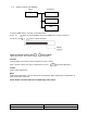
. OSD Architecture 7.1. 19” Monitor Video Function Menu Sub-Menu Video Contrast Brightness Color Tint Press SOURCE to select a video input: Sharpness Press the MENU button to bring up the OSD Menu. Press again to select VIDEO, then press ITEM twice to enter submenu. As shown, press keys to adjust selection. Figure 2. Example Note: In remote control, press key to adjust.
7.2. Video Function (PC Mode Only) Press SOURCE to select a image input: Menu Sub-Menu Video Auto Adjust Press the MENU button to bring up the OSD Menu. Press again to select IMAGE, then press ITEM twice to enter submenu. As shown, press Contrast Brightness keys to adjust selection. H-Position V-Position Note: In remote control, press key to adjust. (After adjustment, the monitor will store new settings) Auto Auto detect screen detail data, such as clock and phase.
7.3. Audio Function (All Models) Menu Sub-Menu Audio Volume Treble Bass Press the MENU button to bring up the OSD Menu. Press again to select AUDIO, then press ITEM twice to enter submenu. As shown, press keys to adjust selection. Figure 3. Example Note: In remote control, press key to adjust. (After adjustment, the monitor will store new settings) Volume Controls built-in as well as external speakers output volume. Note: Volume control can also be adjusted by hot key.
8. LCD Monitor Mounting Guide 8.1. Desktop Mount Adjust the viewing angle of LCD to fit the most comfortable monitoring status. Figure 4. 8.2. Wall / VESA mount Please follow the fix-hole size on back panel to install the LCD to the wall directly, or use a VESA mount. Wall Mounts VESA Mount Figure 5.
9. Device Connectors Figure 6. LCD Connectors a) Connect PC to Monitor through VGA connector as shown in the above picture See Table 1 for support resolutions. b) Connect External device such as DVD or Game Player to Monitor as shown in the above picture c) Connect CCD Camera 1 and 2 to Monitor through Video Input 1 and 2 (BNC Connect) as showing in the above picture Note: Please refer to Specification for auto detection after changing resolution setting. Table 1.
10. Specifications Electrical 45M19H Operating System Brightness Aspect Ratio Picture Diagonal Active Area (W x H) Resolution (H x V) Video Angle Contrast Ratio Video Input Video Output Audio Input/Output In/Out Impedance Power Source Power Consumption Environmental Ambient operating temperature Operating Humidity NTSC/PAL auto detect 300 cd/m2 4:3 19" 13.24” x 11.85” (336.3mm x 301.1mm) 1280 x 1024 (SXGA) Up 800, Down 800, Left 800, Right 800 700:1 2 CH composite video 1Vp-p 75ohm 1 S-Video:Y=1.
11. Appendixes 11.1. Troubleshooting Problem: 1. No power 2. No video or audio 3. Bad video or audio 4. Image not stable 5. Abnormal line 6. Ghost image 7. Desired video disappears Checking: Power not connected, or not engaged Change to correct input channel? Check signal cable? Any interference from other devices? Adjust video control on OSD? Adjust video 11.2. Package Contents A. LCD monitor B. Power cord C. Accessory kit a. DB15 – DB15 VGA cable b. 1/8” male to 1/8” male mini stereo plug cable D.
12. Remote Control 1 4 Video Audio Item 2 5 3 Menu Up 6 Down Source 1. Power Monitor power ON / OFF. At OFF mode, monitor will be on standby status LED - Green Light -- Power On Red Light -- Standby mode 2. Adjust Decrease the value on the OSD menu or turn ON / OFF function 3. Adjust Increase the value on the OSD menu or turn ON / OFF function 4. Item Chose sub menu from Audio / Video / Image Press again to enter selected option 5. Menu OSD menu ON / OFF control 6.
13.Contact To contact Videology Imaging Solutions: USA: Videology Imaging Solutions Inc. 37M Lark Industrial Parkway Greenville, RI 02828 USA Tel: (401) 949-5332 Fax: (401) 949-5276 Europe: Videology Imaging Solutions Europe Liessentstraat 2-B NL-5405 AG Uden The Netherlands Tel: +31 (0) 413 256 261 Fax: +31 (0) 413 251 712 Please also visit our WEB-site at: http://www.videologyinc.