LCD MONITOR USER MANUAL 45M20-1 20” TFT LCD Information may change without notice. This document provides technical information for the user. Videology reserves the right to modify the information in this document as necessary. The customer should make sure that they have the most recent manual version. Videology holds no responsibility for any errors that may appear in this document. Videology Imaging Solutions, Inc.
Table Of Contents 1. 2. Warning ........................................................................................................... 3 Precautions ...................................................................................................... 3 2.1. Safety ....................................................................................................... 3 2.2. Installation ................................................................................................ 3 2.3. Cleaning ...
1. Warning TO REDUCE THE RISK OF FIRE OR ELECTRIC SHOCK: DO NOT EXPOSE THIS PRODUCT TO RAIN OR MOISTURE. DO NOT INSERT ANY METALLIC OBJECT THROUGH VENTILATION GRILLS. CAUTION: Explanation of Graphical Symbols The lightning flash with arrowhead symbol, within an equilateral triangle, is intended to alert the user to the presence of non-insulated dangerous voltage within the product's enclosure that may be of sufficient magnitude to constitute a risk of electric shock to persons.
3. Federal Communications Commission (FCC) Statement This Equipment has been tested and found to comply with the limits for a Class B digital device, pursuant to Part 15 of the FCC rules. These limits are designed to provide reasonable protection against harmful interference in a residential installation. This equipment generates, uses and can radiate radio frequency energy and, if not installed and used in accordance with the instructions, may cause harmful interference to radio communications.
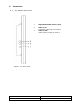
4. Features • • • • • • • • • • • NTSC/PAL Auto Selectable High Contrast 700:1 450 cd/m2 Brightness Fast LCD Response Time of 5ms IR Remote Control Inputs/Outputs: 1 BNC Composite Video Auto Termination 75 Ohms VESA Standard Bracket & Desktop Mount Easy OSD Menu User Interface Wide Viewing Angle (1600 Vertical and Horizontal) Wall Mountable 5. Operating Instructions 5.1. Control 1 2 3 4 Figure 1. 20” LCD Monitor 1. Power Monitor power ON / OFF.
. Connectors 6.1. 20” Monitor Back Panel 1 Regulated 12VDC Power Input 2 Video 1 IN Composite signal input for Video 1 Video 1 OUT Video looping output for Video 1 3 Figure 1.
. OSD Architecture 7.1. 20” Monitor Video Function Menu Sub-Menu Video Contrast Brightness Color Tint Under AVI Mode: Press the ITEM button to bring up the OSD Menu, then press ITEM again to enter submenu. As shown, press Sharpness keys to adjust selection. Figure 2. Example Note: In remote control, press key to adjust. (After adjustment, the monitor will store new settings) Contrast Permits adjustment for contrast between light or dark areas of the picture.
. LCD Monitor Mounting Guide 8.1. Desktop Mount Adjust the viewing angle of LCD to fit the most comfortable monitoring status. Figure 3. 8.2. Wall / VESA mount Please follow the fix-hole size on back panel to install the LCD to the wall directly, or use a VESA mount. Wall Mounts VESA Mount Figure 4.
. Device Connectors Loop out to another video device Camera or other Video source 12VDC input Figure 5.
. Specifications Electrical 45M20-1 Operating System Brightness Aspect Ratio Picture Diagonal Active Area (W x H) Resolution (H x V) Video Angle Contrast Ratio Video Input Video Output In/Out Impedance Power Source Power Consumption NTSC/PAL auto detect 450 cd/m2 4:3 20" 13.24” x 11.85” (336.3mm x 301.1mm) 800 x 600 Up 80°, Down 60°, Left 80°, Right 80° 700:1 1 CH composite video 1Vp-p 75ohm 1 CH composite video 1Vp-p 75ohm Auto termination (75 Ohms) 12VDC/90-260VAC 60Hz/50Hz adaptor 3.
. Appendixes 11.1. Troubleshooting Problem: 1. No power 2. No video or audio 3. Bad video or audio 4. Image not stable 5. Abnormal line 6. Ghost image 7. Desired video disappears Checking: Power not connected, or not engaged Change to correct input channel? Check signal cable? Any interference from other devices? Adjust video control on OSD? Adjust video 11.2. Package Contents A. B. C. D. E.
. Remote Control 1 4 Video Audio Item 2 5 3 Menu Up 6 Down Source 1. Power Monitor power ON / OFF. At OFF mode, monitor will be on standby status LED - Green Light -- Power On Red Light -- Standby mode 2. Adjust Decrease the value on the OSD menu or turn ON / OFF function 3. Adjust Increase the value on the OSD menu or turn ON / OFF function 4. Item Choose sub menu from Video Press again to enter selected option 5. Menu NC 6.
.Contact To contact Videology Imaging Solutions: USA: Videology Imaging Solutions Inc. 37M Lark Industrial Parkway Greenville, RI 02828 USA Tel: (401) 949-5332 Fax: (401) 949-5276 Europe: Videology Imaging Solutions Europe Neutronenlaan 4 NL-5405 NH Uden, Netherlands Tel: +31 (0) 413 256 261 Fax: +31 (0) 413 251 712 Please also visit our WEB-site at: http://www.videologyinc.com/ Please note that data in this application note is subject to change without notification! Videology Imaging Solutions Inc.