Analog Camera User’s Manual CD-960H Important Safeguards and Warnings 1.Electrical safety All installation and operation here should conform to your local electrical safety codes. The power shall conform to the requirement in the SELV (Safety Extra Low Voltage) and the Limited power source is rated 12V DC or 24V AC in the IEC60950-1. We assume no liability or responsibility for all the fires or electrical shock caused by improper handling or installation.
3.Installation Do not apply power to the camera before completing installation. Please install the proper power cut-off device during the installation connection. Always follow the instruction guide the manufacturer recommended. If this product is installed in the ceiling, please make sure the installation position can sustain the min 50N. 4.Qualified engineers needed All the examination and repair work should be done by the qualified service engineers.
1 General Introduction This series analog camera adopts the high sensitivity CCD and advanced circuit design. It is featuring the high quality video, the lowest distortion, low noise and etc. This series product is suitable to be used in surveillance system and video process system. 1.
Auto gain function To output the standard video signal in the different illumination environments, the amplifier needs to adjust in a wide range. The system can enhance the camera sensitivity in low illumination and enhance the video signal output to get the clear and high definition video. SNR It is the ratio value between the signal voltage and the noise voltage. The higher the SNR value, the lower the adverse effect. It is to guarantee the clear video.
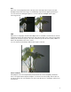
BLC Once there is strong light at the back of the object, the main object video may become dark. Backlight compensation technology is to automatically compensate the light to get vivid video. You can refer to the following two figures to see the result of the backlight compensation technology function.
HLC HLC (High Light Compensation) function can effectively remove the risk of over exposure and guarantee the proper monitor video when there are strong lights. De-noise (Noise reduction) There may be too much noise when you are monitor in the low illumination environments. You can digitally calculate to reduce the noise to get the clear video. Digital image stabilization When the installation position is of much vibration, you can enable this function to guarantee clear and stable video.
Video Output 1Vp-p Composite Output(75Ohm/BNC) SNR Above 60dB Menu LENS Manual/Video/DC SHUTTER/AGC Auto/Manual BACKLIGHT Off/BLC/HLC(High light compensation ) (BLC) WHITE ATW/ ANTI CR /manual/push lock/push/user 1/user 2 BALANCE DAY/NIGHT Auto/external trigger/black and white/color MODE PICTURE Mirror/brightness/contrast/sharpness/hue/gain ADJUST ATR Off/luminance/contrast MOTION Detect sensitivity/block display/area selection DETECT PRIVACY Area selection/color/transparent/mosaic MA
2 Framework 2.1 Dimension Please refer to the following figures for dimension information. See Figure 2-1 and Figure 2-2.
2.2 Side Panel This series analog camera side panel structure is shown as below. See Figure 2-3. 1: Flange-back. 2. Auto aperture port 3.Pedestal to secure the bracket Figure 2-3 1 Flange-back Usually the flange-back has been set to the proper position before it is shipped out of the factory. But sometimes, you may still need to adjust a little bit to let it be suitable for different lens. Please follow the steps listed below: z Secure the lens.
Please refer to the following sheet for detailed information. The video driver auto aperture uses the three pins: Power, Video and GND. The DC driver auto aperture uses the four pins: Damp+, Damp-, driver +, Driver -. 1 Video Power DC Damp- 2 NC Damp+ 3 Video Driver+ 4 GND Driver- 3. The pedestal to secure the bracket It is to install the bracket. Important Please contact our local retailer if you want to use the video drive lens. 2.3 Rear Panel 2.3.
Please refer to the following sheet for detailed information. 1 Menu button Press it for two seconds to call the menu. Use the up/down button to move the function and use the left/right button to select the item. 2 Power indication It is the power indication light. The LED light is on light when the power supply is proper. 3 Video output It is to output analog video signal. 4 Power 5 A,B G,D/N NC, NO “+” is to connect to the positive end. “-” is to connect to the negative end. ” is the ground end.
Figure 2-6 Step 2 Install the camera. Please use the installation pedestal at the top of the camera to turn the camera into the bracket. Step 3 After adjust the camera to proper surveillance position, secure the knob of the bracket to fix the camera. Step 4 Install the lens to the camera head. Adjust the focus and then secure the lens. See 2.5 Hardware Installation Please refer to the following figure for rear panel connection. See Error! Reference source not found..
3 Menu 3.1 Main Menu Please refer to the following sheet for menu information. st ND THE 1 MENU THE 2 LENS TYPE AUTO st MENU THE 1 MENU DC,VIDEO ATR MODE ND THE 2 LUMIN ANCE LOW MIDDLE HIGH CONTR AST LOW MIDLOW MID MIDHIGH HIGH ON AUTO.
ADJUST SYNC LANGUA GE CAMERA RESET CONTRAST 0-255 SHARPNESS 0-255 HUE 0-255 GAIN 0-255 NR MODE Y LEVEL C LEVEL NR OFF,Y/C, Y, C 000-015 000-015 ON INT LL CAMERA ID ENGLISH OFF 3.2 Main Interface Press the menu button for 2 seconds; you can see the OSD menu appear in the monitor. 3.2.1 F481EP and F480CP MENU MENU 3.
Manual It is the manual iris lens. 3.3.2 SHUTTER GAIN The parameter includes: auto , manual . AUTO AUTO SETUP HIGH LUMINANCE MODE BRIGHTNESS LOW LUMINANCE MODE BRIGHTNESS RETURN SHUTTER+AUTO IRIS 028 AGC ×1.00 z z High luminance/low luminance: It is the high brightness/low brightness. Mode: The high luminance parameter includes shutter+auto iris, auto iris, and shutter. The low luminance parameter includes auto gain control (AGC), off. z Brightness: The high luminance parameter ranges from 0 to 255.
User1 z z USER1 WB B-GAIN 030 R-GAIN 033 B-gain: It is to adjust the blue gain. Please use the left/right button to set. The value ranges from 0 to 255. R-gain: It is to adjust the red gain. Please use the left/right button to set. The value ranges from 0 to 255. Note: The user2 setup is the same with the user1. ATW ATW SPEED 239 DELAY CNT 003 ATW FRAME ×1.00 ENVIRONMENT INDOOR RETURN z z z ATW: It is the auto trace white balance.
3.3.5 PICTURE ADJUST Click the confirm button to go to the sub-menu. PICT ADJUST MIRROR BRIGHTNESS CONTRAST SHARPNESS HUE GAIN RETURN z z z OFF 000 128 128 128 128 Mirror: It is to set the horizontal mirror. The parameter includes on, off. Brightness: The value ranges from 0 to 255. Please use the left/right button to setContrast: The value ranges from 0 to 255. Please use the left/right button to set. Sharpness: The value ranges from 0 to 255. Please use the left/right button to set.
z Detect sensitivity: The value ranges from 000 to 127. Please use the left/right button to set. z Block: display: The parameter includes on, off, set . Click the set button; you can use the direction buttons to set the area to display the block. Monitor area: The parameter includes on, off. Area selection: The value ranges from 1/4 to 4/4. Please use the left/right button to set. System max supports 4 areas. You can use the up/down/left/right button to set. Top: The value ranges from 000 to 288.
z z z Burst: The parameter includes on, off. Delay control: The value ranges from 000 to 255. Please use the left/right button to set. Day-night: It is to set the minimum parameter to switch from the day mode to the night mode. The value ranges from 000 to 255. Please use the left/right button to set. z Night-day: It is to set the maximum parameter to switch from the night mode to the day mode. The value ranges from 000 to 255. Please use the left/right button to set.
3.3.11 DIGITAL ZOOM MAG PAN TILT 000-255 000-1023 000-511 RETURN Note This function is null when the digital image stabilization function is on. 3.3.12 CAMERA ID The parameter includes on, off. Select the on button and then click the confirm button, you can go to the sub-menu. Please use the direction buttons to select the character or the function and then click the confirm button to select. CAMERA ID 0001 ABCDEFGHIJKLMNOPQRSTUV W X Y Z 0 1 2 3 4 5 6 7 8 9 —!”# $ % & ’ ()_ ,¥:;< = >?@﹨^*.
3.3.13 RS485 RS485 addr: (1-255): For F481EP series product, please refer to the camera ID setup information for the RS485 setup. RS485 baud rate: 9600bps. RS485 protocol: Auto-adaptive PELCOD, PELCOP, DH-SD. Note: This function is for F481EP, F581EP and F781EP series product only. 3.3.14 SYNC MODE The system supports INT and LL setup. Important The F480CP and F780CP series product do not support the LL synchronization mode. 3.3.15 LANGUAGE The parameter includes: English, Japanese and etc.
Appendix Toxic or Hazardous Materials or Elements Component Name Toxic or Hazardous Materials or Elements Pb Hg Cd Cr VI PBB PBDE Circuit Board Component ○ ○ ○ ○ ○ ○ Device Construction Material ○ ○ ○ ○ ○ ○ Wire and Cable ○ ○ ○ ○ ○ ○ Packing Components Accessories ○ ○ ○ ○ ○ ○ ○ ○ ○ ○ ○ ○ O: Indicates that the concentration of the hazardous substance in all homogeneous materials in the parts is below the relevant threshold of the SJ/T11363-2006 standard.