Vi-D5000 Series CMOR IR Dome User Manual Products covered by this manual Vi-D5030, Vi-D5036 Document Reference Vd601a.doc Date 10-Feb-14 Videoswitch Telephone 01252-851510 Ocean House, Redfields Industrial Park Fax 01252-851296 Redfields Lane, Church Crookham Email sales@videoswitch.co.uk Hants GU52 0RD Web www.videoswitch.co.
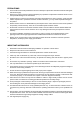
PRECAUTIONS 1. Persons without technical qualifications should not attempt to operate this dome device before reading this manual thoroughly. 2. Remove any power to the dome before attempting any operations or adjustments inside the dome cover to avoid potential damage to the mechanism. 3. Inside the dome cover there are precision optical and electrical devices. Heavy pressure, shock and other sudden adjustments or operations should be avoided. Otherwise, you may cause irreparable damage to the product. 4.
INDEX 1 2 Overview.................................................................................................................................................................... 1 1.1 Model Specific.................................................................................................................................................. 1 1.2 Specification..........................................................................................................................................
4.3.6 Other ......................................................................................................................................................... 25 4.3.7 Alarm ......................................................................................................................................................... 25 4.3.8 Wiper .........................................................................................................................................................
Vi-D5000 IR Dome 1 Overview 1.1 Model Specific Analogue Zoom Digital Zoom TVL BLC WDR Wiper IR Range up to Privacy Tracking Vi-D5030 x30 x12 800 No No Yes 150m No No Vi-D5036 x36 x12 540 Yes Yes Yes 150m Yes No 1.
Vi-D5000 IR Dome 1.3 Performance Features • PWM function. Intelligent IR illumination & power consumption is variable,dependant the zoom factor. • 3D allocation. That screen coordinate location and zoom local are performed at the same time can be available. • Privacy masking. 24 privacy masking areas can be random set (module support). • Supported Protocols. Pelco-D and Pelco-P at 1200, 2400, 4800 or 9600 baud • 4 path patterns. Each path can record 512 different points or 15minutes max duration.
Vi-D5000 IR Dome 1.4 Function Description Alarm Module (Option) Dome camera supports 8 switch alarm inputs, 1 relay output. When the dome camera has detected the alarm closed signal, it will call up the corresponding preset 1 to 8. Tracking (Option) It targets and tracks automatically the moving object in the screen according to the parameter specified by user. The tracking scene, size of object, tracking sensitivity and return time when the object is lost can be settable.
Vi-D5000 IR Dome • Targets are moving quickly • Featureless large area targets, such as wall; • Targets are too dark or faint. Back Light Compensation (some models only) If a bright backlight is present, the target in the picture may appear dark or as a silhouette. BLC enhance the target in the centre of the picture, the dome uses the centre of the pictures to adjust the iris.
Vi-D5000 IR Dome 2 Installation 2.1 Installation Sequence The following sequence is suggested when installing the dome: • Remove hinged cap from the top of the dome, carefully unplugging internal connector. Put dome in a safe place until needed. • Feed umbilical cable through wall, or trunking and then through the chosen bracket • Connect a grounding wire to the green wire of the dome cable (coming from the hinged dome cap).
Vi-D5000 IR Dome 2.2 Connection Details Note A 5m umbilical cable is included 2.3 DIP Switch Settings The dome has DIP switches for setting protocol, baud rate, termination and address. All these settings except termination can be made from within the menu, so typically there is no need to access these switches. If required, the DIP switches are accessible by removing a panel on the side of the dome just above the camera lens. Ensure the waterproof seal is restored when replacing the panel.
Vi-D5000 IR Dome 2.3.1 Preparation Before installation, make sure that the protocol, baud rate and address code used by the product is fully consistent with the control system. The individual DIP switch functions can be seen below: 2.3.2 Address Settings DIP switch SW1 is the address settings of camera. It is a 8-bit switch. Each switch corresponds with 0 or 1 in the Binary code. OFF status means 0 while ON status means 1.
Vi-D5000 IR Dome 2.3.4 RS485 Bus Termination The 8th bit of DIP switch SW2 selects the RS485 bus terminating resistor. This switch should bem set according to the dome’s us as follows: Situation Sw2-8 Single dome ON End of daisy chain of multiple domes, no alarm PCB in power supply ON Mid (i.e. not end) of daisy chain of multiple domes, no alarm PCB in power supply OFF Alarm PCB fitted in PSU. ON Videoswitch Page 8 VD601A.
Vi-D5000 IR Dome 2.4 Bracket Dimensions 2.4.1 Vi-B16 Wall mounting Bracket Note A Vi-B16 wall bracket is included 2.4.2 Vi-B13 Corner Adaptor Bracket Videoswitch Page 9 VD601A.
Vi-D5000 IR Dome 2.4.3 Vi-B14 Pole Adaptor Bracket 2.4.4 Vi-B12 Swan-Neck Bracket Videoswitch Page 10 VD601A.
Vi-D5000 IR Dome 2.4.5 Vi-B15 Pendant (ceiling) Bracket 2.5 Installation of Brackets 2.5.1 Vi-B16 Wall Mounted Fig 1 Installation Wall mounted dome can be used in the hard wall structure whose thickness should be enough to install expansion bolt in indoor and outdoor environment. The wall can bear at least 4 times the weight of the dome. Install wall hanging bracket: a.
Vi-D5000 IR Dome Fig 2 b. As shown in fig 3, fix the wall hanging bracket on the wall with wire and cable through it. Fig 3 2.5.2 Vi-B13 Corner Mount Adaptor Fig 11 Installation Corner mounted dome can be used in the hard wall structure with an angle of 90° whose thickness should be enough to install expansion bolt in indoor and outdoor environment. The wall can bear at least 4 times the weight of the dome. Install corner mounted attachment and wall hanging bracket: a.
Vi-D5000 IR Dome Fig 12 b. As shown in fig 13, use M8 screw nut to fix the base of corner mounted on the wall with all cables through the centre holes of the corner mounted, marine glue and bracket. Enough wiring length should be left. Fig 13 c. As shown in fig 14, fix the wall hanging bracket with all cables power through it on the corner mounted attachment. Videoswitch Page 13 VD601A.
Vi-D5000 IR Dome Fig 14 2.5.3 Vi-B14 Pole Mount Adaptor Fig 15 Installation Pole mounted dome can be used in the hard pole structure in indoor and outdoor environment whose diameter should match the installation size of stainless hose clamps. Factory default is 6 inches stainless hose clamps (fit φ130-152mm pillar). The pole structure can bear at least 4 times the weight of the dome. Install corner mounted attachment and wall hanging bracket: a.
Vi-D5000 IR Dome Fig 16 b. As shown in fig 17, fix the wall hanging bracket with all cables through it on the pole mounted attachment. Fig 17 2.5.4 Vi-B15 Pendant (ceiling) Bracket Fig 18 Videoswitch Page 15 VD601A.
Vi-D5000 IR Dome Installation Ceiling mounted dome with thick pole can be used in the hard ceiling structure whose thickness should be enough to install expansion bolt in indoor and outdoor environment. The ceiling can bear at least 4 times the weight of the dome. Install the base of ceiling and boom: a. As shown in fig 19, with the installation holes in the base of ceiling as pattern, draw punched locations in the ceiling and punch to install M6 expansion bolt. Fig 19 b.
Vi-D5000 IR Dome Fig 21 Note If the dome is used in outdoor conditions use silicone rubber around the joint sleeve and connector of the boom to be sure it is water proof. Videoswitch Page 17 VD601A.
Vi-D5000 IR Dome 3 Operation 3.1 Power Up Action IR CAMERA PROTOCOL COMM DOME ID MODULE VERSION PAN MOTOR TILT MOTOR When initialising the system, the operation run in 2 seconds. PELCO-D/P 2400.N.8.1 001 V1.2 INIT INIT When restoring out-of-factory settings, please wait patiently. The operation will run for 1 minute. This left figure shows the initialising state of the pan/tilt motor of speed dome camera. POWER ON IR CAMERA PROTOCOL COMM DOME ID MODULE VERSION PAN MOTOR TILT MOTOR PELCO-D/P 2400.N.8.
Vi-D5000 IR Dome 3.2 Basic Function Pan & Tilt Control Control joystick or keys for up, down, left and right movement Zoom • Press ZOOM- button to make the lens further and see more of the scene. • Press ZOOM+ button to make the lens closer and magnify the scene. Focus • After FOCUS- button is pressed, the objects closer will become clearer while objects further away will become blurred. • After FOCUS+ button is pressed, object far away will become clearer while objects closer will be blurred.
Vi-D5000 IR Dome 3.3 Special Function Presets The follow presets are predefined as special function. Use Call Preset or Goto Preset to operate those functions. Note that dedicated keys are provided on the Videoswitch Vi-K2000 keyboard for these functions when protocol CMOR D5 is selected.
Vi-D5000 IR Dome • 3.4.2 IR Display: ☀means the IR is turned on. indicates the IR output power. Menu Mode • Call preset 95 to enter the menu, call preset 94 to exit the menu. • Up or Down: Move the option of the menu, change the value on the menu. • Right: Enter the option, select the item or confirm. • Left: Return to main menu or cancel Notes “-” is the cursor showing the currently selected option. Use up and down to change.
Vi-D5000 IR Dome 4 OSD Menu 4.1 Menu Structure Videoswitch Page 22 VD601A.
Vi-D5000 IR Dome 4.2 System • PROTOCOL: Display the protocol of the dome • COMM: Communication parameters: Baud rate, Parity ,bit, Data bits, Stop bits. • DOME ID: Display the dome address. The range is 000-255. • MODULE: Display the brand and model of camera. • VERSION: Firmware version of dome. • Set comms parameters in this menu instead of using DIP switches • Set passord to protect menu 4.2.
Vi-D5000 IR Dome • A/B SCAN Scan between A and B points • 360° SCAN Scan through 360° 4.3.3 Guard Tour This dome camera can set 4 groups of guard tour. Each group has 16 points and each point can be set alone the dwell time and tour speed. • GUARD TOUR ID: Select group 1 - 4 • CALL GUARD TOUR: Call the guard tour ID edited successfully. • ID: The tour sequence of guard tour group. Its range is 1-16. • POINT: The preset of guard tour. Its range is 01-64 settable.
Vi-D5000 IR Dome 4. Shake the joystick to aim at the object. Use the ZONE WIDE and ZONE TELE keys in the keyboard to adjust the size of picture. And use iris OPEN and CLOSE keys to adjust the size of mask. Call preset 1 to save and exit and call preset 2 to exit directly. Note The mask size is better more than double the target size. Setting mask is associated with the pitch angle which is advised equal to or less than 45°by the factory. 4.3.
Vi-D5000 IR Dome dome camera will adjust automatically the camera zoom and keep pace with the scene images according to the size of moving object. Note • • The practical effectiveness of tracking function has a lot to do with application environment. The tracking function ON will influence the effect of privacy masking. 4.4 Camera • ZOOM LIMIT: Display the maximum zoom position, which relates to that digital zoom is OFF or ON.
Vi-D5000 IR Dome • DAY/NIGHT TIME: Selectable range is 2 - 15 seconds • IR PWR STBY: IR power standby can be set to 1-9 level when the dome camera is in idle time, which can improve the life of IR lamps. • IR TIME STBY: The time interval from the no any operation to dome camera to the effective operation to it. • ILLUMINATION ON: Its range is 0-25 level. In the IR mode of auto, when the “ILLUMINATION ON” is lower than ”AMBIENT LIGHT”, the picture turns to colour and IR lamps close.
Vi-D5000 IR Dome Note When the schedule is set, there can not be overlap part in periods of time. The system will respond at priority to the first triggered schedule, only after which is completed, it will respond other schedules. Please make sure there is only one schedule at some certain period. System will return to preset 1 after completing schedule. 4.8 Language • LANGUAGE: Menu language can be set here 4.
Vi-D5000 IR Dome 5 Appendices 5.1 Anti-lightning, Anti-surge This product is protected against air discharge and lightning with TVS tube technology which can effectively prevent the transient lightning below 3000V surge voltage and damage caused by other types of pulse signals.
Vi-D5000 IR Dome 5.2 Clean Camera Window In order to assure a clear image of dome, the under cover of dome should be cleaned regularly. • Be careful when cleaning and hold the outer ring of under cover by hands to avoid directly touching with it. Because the acid sweat of finger membrane may corrode the surface coating of under cover. Hard tool scratching the under cover may lead to blurring the images of dome so that affecting image quality.
Vi-D5000 IR Dome 5.4 Address Code Mapping Table SW1 DIP Switch sets the dome address, which using binary encoded. The 8th is the top bits, and 1st is the lowest bits. If a switch to ON that is a logical “1”. If a switch is OFF that is a logical “0”. 5.4.
Vi-D5000 IR Dome 5.4.
Vi-D5000 IR Dome 6 Problem solving Issue After power is applied, there is no motion (self-test) and no video image Possible Reason Cable harness is improperly connected Input power voltage is too low Power supply is not work Self-test is normal, but cannot control dome.
Vi-D5000 IR Dome Copyright Statement This copyright belongs to the manufacturer. Do not copy the contents of this book in any form or by any means without permission. The company follows the policy of continuous development. Therefore, the company reserves the right to modify or improve the products described in this manual without notice. The content of manual is offered according to the "current state".