VDM Digital Recorder User Manual Products covered by this manual: Cameras / Hard Drive Capacity 9 16 160 Gbytes VDM-9G160 VDM-16G160 320 Gbytes VDM-9G320 VDM-16G320 500 Gbytes VDM-9G500 VDM-16G500 600 Gbytes VDM-9G600 VDM-16G600 800 Gbytes VDM-9G800 VDM-16G800 Document Reference Date Firmware Vk603t 14/11/2005 From VDM001GB, VDM002AA Videoswitch Telephone 01252-851510 Ocean House, Redfields Industrial Park Fax 01252-851296 Redfields Lane, Church Crookham Email sales@videoswi
Videoswitch Vdm601t.
Videoswitch VDM Digital Recorder Contents: 1 Overview.............................................................................................................................................. 1 1.1 The VDM Digital Recorder......................................................................................................................................................1 1.2 The Front Panel ...........................................................................................................
Videoswitch VDM Digital Recorder Replaying Incidents .............................................................................................................................................................. 24 7.8 7.8.1 Selecting an Incident........................................................................................................................................................ 24 7.8.2 Go to the start of the current incident...........................................................
Videoswitch 10.2.8 VDM Digital Recorder Show Camera Titles .........................................................................................................................................................35 10.2.8.1 Full Screen Titles ............................................................................................................................................35 10.2.8.2 PIP Titles......................................................................................................
Videoswitch 10.4.4.7.4 10.4.4.7.5 10.4.4.8 10.4.5 10.4.6 10.4.7 11 Restore after Activity/Alarm....................................................................................................................... 43 Display Active Pixels ...................................................................................................................................... 43 Critical Alerts .................................................................................................................
Videoswitch 12.10 13 VDM Digital Recorder Safety....................................................................................................................................................................................53 Notes.................................................................................................................................................. 54 Vdm601t.
Videoswitch VDM Digital Recorder 1 Overview 1.1 The VDM Digital Recorder The VDM Digital Recorder provides a one-box solution for multiplexing, digital recording of video images from up to 16 cameras, CD backup and remote dial-up viewing of live or recorded images. • All you need for a digital recording system is the VDM recorder, up to 16 cameras and a display monitor. This set-up will permit the video images from all the cameras to be recorded onto hard disc for a period of typically 31 days.
Videoswitch 1.
Videoswitch 1.
Videoswitch 1.4 VDM Digital Recorder Operating Modes The VDM Digital Recorder is controlled via the front panel keys. All status information is displayed on the main monitor. The VDM has a number of operating modes that are called up during the set-up and operation of the system. Each of these modes has a different easily identifiable screen display. Note that the camera-select keys are used for entering numbers in some of the modes, and the camera 10 key is used to enter zero.
Videoswitch 1.
Videoswitch 1.6 VDM Digital Recorder Menu Structure Í Í The following sections summarise the menu structure. Note that the menu may vary slightly between different versions of firmware installed in the VDM. Press the SETUP key to enter and exit the menu system. Use the cursor keys , , Í and to navigate through the menus. The DEFAULT key is very useful within the menus as it is used to set the currently selected menu item to a default condition.
Videoswitch 1.
Videoswitch 1.8 VDM Digital Recorder Supervisor Menu Supervisor Menu Covert Permission (Main) Covert Cameras (Main) Covert Cameras (Spot) Passwords Supervisor Password User Password Incident Password Playback Password Keyboard Password Password AccessTimeout Erase Event List Event List Needs Password Vdm601t.
Videoswitch 1.
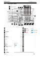
Videoswitch VDM Digital Recorder 2 Installation 2.1 Connecting Up (4 Camera example) 101 75 Ohms IN 100 102 103 106 104 105 107 Make these Connections… 100 101 102 103 104 105 106 107 Connect the video input of the Monitor to the main monitor output of the VDM using a BNC cable Make sure that the monitor termination is switched on (i.e.
Videoswitch 2.2 VDM Digital Recorder Setting Date and Time For proper operation of the VDM Digital Recorder it is essential that the date and time are set correctly. If the displayed date and time is incorrect, set it as follows (numbers refer to Front Panel diagram 1.2): Follow these steps… Í Press the SETUP key to enter the menu screen.
Videoswitch VDM Digital Recorder 3 Recording Unless specifically configured otherwise, the system will always be recording images from all cameras. Even when you are playing back images, the system will continue recording. When the record LED on the Hard drive is on, this indicates that recording is taking place. RECORD 3.1 Update Rates This table gives an indication of the overall update rate in images per second that will apply for different Image Retention settings (see section 10.4.3.1.
Videoswitch VDM Digital Recorder 4 Remote Access 4.1 Configurations The various standard remote access configurations are illustrated in the following diagrams. 4.1.1 PSTN Standard telephone lines (PSTN) provide the lowest cost and easiest method of achieving remote viewing of images. A VDM/PSTN (modem) module must be installed in the VDM and the PC must have a standard internal (or external) modem fitted. A telephone socket is required both at the VDM and at the PC end.
Videoswitch VDM Digital Recorder Any number of PCs can access any number of VDMs on a one-to-one basis, subject to the size of the network. The network can be an independent network for the CCTV, or an existing computer network. In the latter case, the network administrator may need to designate suitable IP addresses for the VDM(s) that avoid conflicts with the PCs and printers on the network. VDM + VDM/ETHER-1 CAT5 CABLE CAT5 CABLE PC + Ethernet Interfa ce + “VDM Connect” ETHERNET HUB or SWITCH 4.
Videoswitch 4.2 VDM Digital Recorder Option Modules The following option modules are available for remote access. Any one of these modules may be either prefitted into the VDM or may be retro fitted. • VDM/PSTN Connect via a PSTN (standard telephone) line • VDM/ISDN A faster connection may be achieved via an ISDN digital line. • VDM/ETHER-1 This module allows one or more VDMs to be monitored on a local area network (10baseT or 100baseT Ethernet, using TCP/IP protocol). 4.2.
Videoswitch 4.2.2 VDM Digital Recorder VDM Firmware Upgrades The firmware revision in the VDM must be VDM001G3 or later. Upgrade using an upgrade CD as described in section 10.2.10. Refer to section 10.4.7.4 for details of the menu settings necessary for remote access operation. 4.3 PC Software In order to remotely view images on a PC, the software “VI-Connect” must first be installed on the PC that will be used for viewing. 4.3.
Videoswitch 4.3.4 VDM Digital Recorder Using VI-Connect Any VDM that is in the list of sites, may be accessed as follows: • Click on “Connection” • Select the VDM you want • Click on “Connect”. The “Receiving” message will appear in the bottom bar and images will start to appear once connection has been established. Click on the following buttons… • Camera buttons 1, 2, 3 etc.
Videoswitch VDM Digital Recorder 5 Routine Checks Although the system is intended for continuous un-attended operation, it is recommended that the user regularly check that images from all cameras replay correctly. Any potential problems with the cameras or recording system will then be detected as soon as possible, rather than continuing un-noticed until a critical incident needs to be recalled from the system.
Videoswitch VDM Digital Recorder 6 Viewing Live Images 6.1 Enter Live Mode Press the LIVE key to enter LIVE mode 6.2 Live Display Modes 6.2.1 Full Screen Main Monitor Select full screen views of different cameras by pressing the keys Camera 1, 2, 3 etc 1..16 6.2.2 Spot Monitor The spot monitor output is a completely independent monitor output that always displays a full screen live image. ALT and 6.2.3 1..
Videoswitch 6.2.5 VDM Digital Recorder 9-way and 16-way Multi-Screen If you have a VDM-9 or VDM-16, press multi-screen key to view nine pictures at once on the screen. If you have a VDM-16, press multi-screen key again to view sixteen pictures at once on the screen. 6.2.6 Zoom To magnify a full-screen live image, you must enter LIVE mode (section 6.
Videoswitch VDM Digital Recorder 7 Replaying Recorded Images 7.1 Enter PLAY mode 7.1.1 Replay from Hard Drive(s) If there is no CD in the CD drive, playback will be from the hard drive(s). Before being able to replay, you may need to locate valid images using the SEARCH, EVENT or INCIDENTS keys. Press any of the PLAY keys to enter PLAY mode. Once in PLAY mode, these play keys may be used to move forwards and backwards through the recorded video images.
Videoswitch VDM Digital Recorder Play forwards at fast speed. Press repeatedly to increase the replay speed. Play backwards at fast speed. Press repeatedly to increase the replay speed. Pause at current image. 7.3 Replay Display Modes Different cameras may be selected for display while in PLAY mode as follows: 7.3.1 Full Screen (Main Monitor) 1..16 Select full screen views of different cameras by pressing the keys Camera 1, 2, 3 etc 7.3.
Videoswitch 1..10 VDM Digital Recorder Enter the required date and time using the number keys 1, 2, 3, 4, 5, 6, 7, 8, 9 and zero Press any of the PLAY keys to enter PLAY mode at the specified date and time SEARCH Alternatively, to exit without searching, press the search key again. The format for the date and time is DD/MM/YY HH:MM:SS where: • DD is the day of the month (00 to 31), • MM is the month (01 to 12), • YY is the year (e.g.
Videoswitch 7.6 VDM Digital Recorder Recalling Events The event log records the date and time of various events: • On power-up, the system records an event in the event log, • If activity detection has been enabled and activity occurs • If external alarm inputs are being used • If a system alert occurs (e.g.
Videoswitch VDM Digital Recorder If you wish to play back images from the date and time of the selected incident* press one of the PLAY keys. INCIDENTS To exit without replaying an event, press the event key *If the selected incident is too old and has therefore been over-written on the hard drive(s), it will not be possible to re-play it. 7.8.2 Go to the start of the current incident You must already be in play mode for these operations. ALT 7.8.3 ALT Vdm601t.
Videoswitch VDM Digital Recorder 8 Archiving Images onto CD Sections of the recording that you wish to store onto CD are called “incidents”. Up to ten incidents may be set. These may then be recorded onto a CD. Incidents are marked while the VDM is in PLAY mode. The INCIDENT mode displays the start and end time of any incidents that have been marked, and the total amount of space on the CD that will be used (in Megabytes). This must not exceed the available size of the CD (around 650 to 750 Mbytes).
Videoswitch 8.2.4 VDM Digital Recorder Reduce an Incident by Moving the Start ALT + Í 8.2.5 Press the ALT and Í keys to move the start of an incident forward by 100 images Reduce an Incident by Moving the Start or End Press the NO key to reduce the size of the incident by 100 images. The reduction will be at the start or end depending on whether the Í or key was used last. NO Í 8.
Videoswitch Select a spare incident (or an existing incident if you wish to move the marker) Í Í ALT VDM Digital Recorder Press the ALT and SET END keys. The time and date of the end of the incident will added to the list and 8.4 Selecting Incidents Up to ten incidents may be marked, and any number of these may be selected for copying onto CD.
Videoswitch 8.7 VDM Digital Recorder Replaying a CD A CD recorded on a VDM Digital Recorder may be played back: • In any VDM (section 7.1.2) or • In a PC directly. Replay software is automatically recorded onto the CD together with the image information so that the CD will play on a PC without any software installation on the PC being required. The CD should auto-run when placed in a PC, unless auto-run is disabled in the PC configuration. • The file on the CD with extension “.
Videoswitch VDM Digital Recorder 9 Information Screens 9.1 Viewing Drive Information To see what drives are fitted and whether a CD is in the CD drive press these keys: and ALT DRIVES Press ALT and DRIVES to see whether a CD has been detected in the CD drive, what size and type hard disc drives are fitted, and which hard drive is currently allocated for recording.
Videoswitch 9.3 VDM Digital Recorder System Information and ALT SETUP Press ALT and SETUP to view system information.
Videoswitch VDM Digital Recorder 10 Setup The SETUP menu is used to access the CD writer functions and all system configuration options. Once in the menu system, a number of the keys have dedicated functions for navigation around the menu. The functions of these keys are described on this page. There is a summary of the menu system in section 1.6, and more details in the following section of this manual [pending up-issue].
Videoswitch 10.2 User Menu 10.2.1 Incident Options 10.2.1.1 VDM Digital Recorder Erase CD This option erases all information on a CD-RW in the CD drive. Press YES to erase the CD-RW. Note that CDR discs cannot be erased. For this reason they are preferred for recordings of important evidence. 10.2.1.2 Filename You may specify (numerical) filename to be used when storing incidents. Use 1-10 keys (10 key is used to enter zero).
Videoswitch VDM Digital Recorder 10.2.5.1 Main Monitor Mode The display mode of the main monitor following power-up may be specified here. 10.2.5.2 Sequence Main The sequencing of the main monitor following power-up may be specified here. 10.2.5.3 Sequence Spot (Day) The sequencing of the spot monitor following power-up may be specified here. This setting applies if the time is within a period specified by the Daytime timers (See section 10.4.2.4). 10.2.5.
Videoswitch VDM Digital Recorder 10.2.6.7 Always Interlace If set to “Yes”, an interlaced image is always output on the Main Monitor. Although this results in some degree of flicker in the text screens, this option is necessary for some video capture cards to operate correctly. The normal setting is “No”. 10.2.7 Titles 10.2.7.1 Digital Recorder Title A title may be entered for the Digital Recorder. This is displayed at the top of the screen (not in menu or play modes).
Videoswitch • Show Numbers • Show Text 10.2.9 VDM Digital Recorder Text Alignment The vertical and horizontal alignment of the text may be adjusted using the cursor keys such that all the text is visible on monitors that over-scan. Press the DEFAULT key for standard positioning, and the NO key to exit. 10.2.10 Time/Date Alignment The vertical and horizontal alignment of the time and date may be adjusted using the cursor keys to suit the user.
Videoswitch 10.3 Supervisor Menu 10.3.1 Covert Permission (Main) VDM Digital Recorder This option allows covert cameras to be replayed. 10.3.2 Covert Cameras (Main) This is the list of cameras that are hidden from view on the main monitor (except when enabled in play mode as above). 10.3.3 Covert Cameras (Spot) This is the list of cameras that are hidden from view on the spot monitor. 10.3.
Videoswitch VDM Digital Recorder 10.3.4.1 Supervisor Password This password, if set to a non-zero value, protects the Supervisor menu. On entering this password, access is granted to the Supervisor menu, User Menu, Incident Menu, Playback functions and the Keyboard. 10.3.4.2 User Password This password, if set to a non-zero value, protects the User menu. On entering this password, access is granted to the User Menu, Incident Menu, Playback functions and the Keyboard. 10.3.4.
Videoswitch 10.4 Engineer Menu 10.4.1 Date and Time 10.4.1.1 VDM Digital Recorder Summer/Winter Time When the clocks change between wintertime and summertime, the DATE/TIME setting must not be changed. Instead, the Summer/Wintertime setting should be used. In the UK and the rest of Europe, the default AUTO Summer/Wintertime setting ensures that this happens automatically at the correct dates so the user requires no action. 10.4.1.
Videoswitch VDM Digital Recorder 10.4.2.3 Activity Enable/Disable Activity detection is be enabled for particular times of day, for each day of the week Examples: • All day, enter: 00:00 23:59 • Typical Working Hours (08:30 to 17:30), enter: 08:30 17:30 • Morning and evening (00:00 to 08:30 and 17:30 to 00:00), enter: 17:30 08:30 10.4.2.4 Daytime The Daytime timer allows the spot monitor to change camera and/or start/stop sequencing at particular times of day.
Videoswitch VDM Digital Recorder Note that if the Image Size Control (section 10.4.3.4.2) is set to Variable, the exact size of the image, for a particular quality setting, depends on the level of detail the camera is looking at. Simple scenes, such as empty or dark rooms or car parks, result in smaller image sizes, thereby saving disc space and allowing faster updates. Conversely, where more details exist, the image size will correspondingly increase. 10.4.3.2 Custom Mode 10.4.3.2.
Videoswitch VDM Digital Recorder Notes: The Relay Hold Timer extends the time for which the Alarm/Activity recording mode is applied. Any cameras which do not have video are automatically excluded even if specified in any of the camera select lists. 10.4.3.3.5 Storage Allocation (%) An allocation may be made here for reserving disc space for alarm and activities. This enables the automatic Image Retention calculator to make an allowance for alarms.
Videoswitch VDM Digital Recorder The DEFAULT key can be used to turn all zones on or off. The YES key turns the selected row on and off. 10.4.4.2 Enable Activity The activity detector for each camera may be set to be either always active, or active only during the Activity periods specified (section 10.4.2.3). 10.4.4.3 Alarm Polarities Each alarm input may be set to normally open or normally closed.
Videoswitch 10.4.5 VDM Digital Recorder Critical Alerts If a fault condition is detected by the VDM, a red “Critical Alert” message appears on the screen. The alert is also stored in the alert log. If the alert options have been set up correctly, an alert message indicates that engineer attention is required to determine the source of the problem. The red alert message may be cancelled by pressing the EVENT key and entering the event screen.
Videoswitch VDM Digital Recorder 10.4.7.2 Remote Password A password may be set to prevent unauthorised remote access. Set to all zeros if the revision of remote access software (“VI-Connect”) used does not support password protection. 10.4.7.3 Remote Covert Cameras Cameras may each be set as visible or hidden (covert) when accessed remotely via PSTN or ISDN. Note that only cameras that are currently recording may be viewed live. 10.4.7.4 Network Settings 10.4.7.4.
Videoswitch • VDM Digital Recorder MSN - The Multiple Subscriber Numbering option ensures that the incoming call is only answered if it is of the correct type (i.e. V120) and the last digits of the called number match the “ISDN MSN/Sub-Address” (section 10.4.7.4.8). 10.4.7.4.8 ISDN MSN/Sub-Address Up to three digits may be entered using the Camera 1.16 keys to specify either the Sub-Address or MSN number as described above. Press DEFAULT key clear this setting. 10.4.7.4.
Videoswitch 10.4.8.3.2 VDM Digital Recorder Erase Hard Drive 2 Erase all image indexes on hard drive 2 (upper). The hard drive will appear blank in the drive information screen. 10.4.8.3.3 Erase Both Hard Drives Erase all image indexes on both hard drives. The hard drives will appear blank in the drive information screen. 10.4.8.3.4 Upgrades need engineer password? All firmware upgrades are performed via the User Menu (section 10.2.10).
Videoswitch VDM Digital Recorder 11 Changing Hard Drives The VDM Digital Recorders are supplied with two removable hard drive drawers. Depending on the configuration, hard disc drives may be fitted in both of these drawers, or just one or in neither. The VDM requires at least one hard drive in order to be capable of recording images. A hard drive may be changed while the unit is powered up.
Videoswitch VDM Digital Recorder 12 Specifications 12.1 Image Capture and Storage Displayed Image Format 720 x 576 Pixels, 16 Million colours Compressed Image Format 720 x 288 Pixels, 16 Million colours Sample rate 13.5Mhz Image Compression System Wavelet 12.2 Connectors 12.2.1 Power Input Main input is switch-selectable 230/115 Volts AC 50/60Hz, 100W maximum. Check switch setting before applying power or damage may occur. 12.2.
Videoswitch 12.3.2 VDM Digital Recorder ISDN Protocol V120 Data Rate 64kbit/sec Typical image update time (8K image) 1.4 seconds MSN support Yes Sub-Addressing support Yes 12.3.3 Ethernet Interface 10BaseT or 100BaseT Protocol TCP/IP Data Rate 300kbit/sec Typical Ethernet bandwidth required per VDM 0.5 Mbit/sec Typical image update time (8K image) 0.2 seconds Vdm601t.
Videoswitch 12.3.4 VDM Digital Recorder Alarms and Keyboard 13 12 11 10 9 8 7 6 5 4 3 2 1 25 24 24 22 21 20 19 18 17 16 15 14 1 2 3 4 5 6 7 8 9 10 11 12 13 Pin Function GND Alarm Input 15 RS422 OutRS422 InAlarm Input 9 Alarm Input 11 Alarm Input 13 Alarm Input 1 Alarm Input 3 Alarm Input 5 Alarm Input 7 Relay 2 Relay 1 12.3.
Videoswitch 12.3.6 VDM Digital Recorder Parallel Port (Printer) 13 12 11 10 9 8 7 6 5 4 3 2 1 25 24 24 22 21 20 19 18 17 16 15 14 1 2 3 4 5 6 7 8 9 10 11 12 13 Pin Function STRB\ Data 0 Data 1 Data 2 Data 3 Data 4 Data 5 Data 6 Data 7 ACK\ BUSY PE SEL 14 15 16 17 18 19 20 21 22 23 24 25 Pin Function AUTOFD\ ERROR\ INIT\ SEL IN\ GND GND GND GND GND GND GND GND Mating plug required: 25-way male D-type. 12.
Videoswitch 12.5 Power Requirements Voltage Power 12.6 VDM Digital Recorder 115Vac or 240Vac 50/60 Hz 100W maximum CE Marking This product is CE marked. It has been fully tested and complies with 89/336/EEC Electromagnetic Compatibility and 73/23/EEC Low Voltage directives, and with EN 60950:2000 safety standards. Warning: This is a Class A product. In a domestic environment this product may cause radio interference in which case the user may be required to take adequate measures. 12.
Videoswitch VDM Digital Recorder 13 Notes Vdm601t.
Videoswitch Vdm601t.