Vi-POSCON Installation Guide Vi-POSCON Installation Guide Document Reference Date Pos601a.doc 20/03/2007 Videoswitch Telephone 01252-851510 Ocean House, Redfields Industrial Park Fax 01252-851296 Redfields Lane, Church Crookham Email sales@videoswitch.co.uk Hants GU52 0RD Web www.videoswitch.co.uk Videoswitch 1 Pos601a.
Vi-POSCON Installation Guide Videoswitch 2 Pos601a.
Vi-POSCON Installation Guide Contents 1 2 CAUTIONS ............................................................................................................................ 5 About this Guide .................................................................................................................... 5 2.1 If you need assistance, call… ......................................................................................... 5 3 Introduction ........................................................
Vi-POSCON Installation Guide 10.1 10.2 Regulatory Compliance................................................................................................. 40 Other Declarations ........................................................................................................ 40 Videoswitch 4 Pos601a.
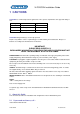
Vi-POSCON Installation Guide 1 CAUTIONS CAUTION: For continued protection against risk of fire, replace only with the same type and rating of fuse. PCB Legend Fuse F1 Value 1A @ 250V Type Ceramic "F" Fuse F2 500mA @ 250V Ceramic "L" Fuse F3 500mA @ 250V Ceramic "L" CAUTION: Danger if battery is incorrectly replaced. Replace only with the same or equivalent type recommended by the manufacturer. Dispose of batteries according to the manufacturer's instructions.
Vi-POSCON Installation Guide 3 Introduction The Vi-POSCON System is a point-of-sale exception monitoring device that connects to a store's cash registers and camera surveillance system. The Vi-POSCON System monitors EPoS (Electronic Point-of-Sale or cash register) terminal activity and documents suspicious sales transactions. It does this by monitoring the register data for up to 10 sales transactions that the operator has designated as exception events.
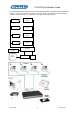
Vi-POSCON Installation Guide 4 System Components The following illustration shows the components of a typical Vi-POSCON System for a single register installation. Vi-POSCON can monitor up to four cash registers with a single DVR and video monitor. Depending upon the specific needs of each installation, the system setup will vary from site to site. The Vi-POSCON components required for a single cash register installation are described below. The printer is optional, but is typically included.
Vi-POSCON Installation Guide The following illustration shows the maximum Vi-POSCON System configuration with one DVR and monitor. You can connect up to four registers, cameras, DVRs, and monitors to the Vi-POSCON controller. A Printer Interface is required for each register you want to monitor.
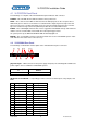
Vi-POSCON Installation Guide 4.1 Vi-POSCON Front Panel The following is a escription of the Vi-POSCON front panel indicators and connector. POWER – This red LED, when lit, indicates that the unit is powered on. DATA – These four tri-colour LEDs are linked to the four data input ports on the rear panel.
Vi-POSCON Installation Guide 15 unassigned 34 Alarm GND 16 Alarm Input 4 35 Alarm GND 17 Alarm Input 3 36 Alarm GND 18 Alarm Input 2 37 Alarm GND 19 Alarm Input 1 * NO = Normally Open; NC = Normally Closed Relay 1 is associated with Channel 1, Relay 2 with Channel 2, Relay 3 with Channel 3, and Relay 4 with Channel 4. Relay 5 is associated with the Main Monitor output and if Vi-POSCON is configured as a standalone system, this relay should be connected to the Alarm Input of the time-lapse DVR.
Vi-POSCON Installation Guide Video Input Jumper Notes 1 JP5 2 JP4 3 JP3 4 JP2 For future use AUX JP1 [J] Video Output (1 through 4) – four BNC connectors for video output. The video output signals include the text overlay from the EPoS. 4.3 The Vi-POSCON Text Overlay The monitor text overlay of the Vi-POSCON System is similar to the following illustration. The surveillance scene is omitted for clarity.
Vi-POSCON Installation Guide 5 Installation 5.1 Introduction This section describes how to install and configure a single controller Vi-POSCON System. 5.2 Before You Begin Verify that all the equipment has arrived. Verify that the unit shipped is the right configuration for the store. Be organized. Unpack components in the back room. At the installation area, lay out parts in the order you will need them. Do not clutter traffic areas or cause a safety hazard. 5.3 Pre-Installation Checklist 5.3.1.1.
Vi-POSCON Installation Guide 5.4 Controller Installation Kits and Tools 5.4.
Vi-POSCON Installation Guide 5.5 Installing a Vi-POSCON System Before installing the Vi-POSCON controller, conduct a site survey with the customer and a salesperson. For more information on the site survey, see the Pre-Installation Checklist (page 6). Determine where to install the controller, then continue with the following installation instructions. Note: Before installing the Vi-POSCON controller, review the system connection diagram in Figures 2 and 3. Verify pre-installation work.
Vi-POSCON Installation Guide Note: If you are installing the 40-column dot-matrix Epson TM-U200D printer option, you must set the 4-position DIP switch located beneath the inspection plate on the bottom of the printer. Set the switch to the following positions: 1=OFF, 2=OFF, 3=OFF, and 4=ON. Note: If you are installing the 40-column Epson TM-T88 Thermal printer option, you must set the 8position DIP switches located beneath the inspection plate on the bottom of the printer.
Vi-POSCON Installation Guide 1 1 2 2 3 3 Jumper position for RS-232 operation P12 P11 Jumper position for RS-485 operation P11 P12 Figure 1. Controller PCB 1 JP3 1 JP1 JP5 JP4 F1 P9 P10 JP2 P7 U48 R25 R51 R77 R103 U47 F3 F2 U36 U39 C5 U1 BT1 U2 U37 U3 P8 P5 CAUTION: Replace fuses only with the same type and rating. PCB Legend Fuse F1 Fuse F2 Fuse F3 Videoswitch Value Type 1A @ 250V 500mA @ 250V 500mA @ 250V Ceramic "F" Ceramic "L" Ceramic "L" 16 Pos601a.
Vi-POSCON Installation Guide Figure 2. System Connection Diagram with four registers Videoswitch 17 Pos601a.
Vi-POSCON Installation Guide 5.6 Power-Up Sequence This section describes the steps for applying power to the Vi-POSCON System. CAUTION: Do not apply power to the Vi-POSCON controller or to the printer interface until directed to do so. Plug the power cord of the following components (as applicable) into an AC outlet and turn on their power switch: Cash registers Monitor DVR Cameras Verify that these components are powered-on.
Vi-POSCON Installation Guide 6 Configuring the Vi-POSCON System This section describes the procedures for configuring the Vi-POSCON System. You use the mouse to access the menus, make selections, and input settings. The term click as used in these instructions means to press and release the left mouse button. When necessary, the instructions will specify to "click the right mouse button". Following is a suggested sequence of events for configuring your Vi-POSCON System.
Vi-POSCON Installation Guide 7 The Vi-POSCON Service Menu This section details the procedures for using the Service Menu options. The Options are described in the order in which they appear on the menu. You can access the Service Menu from the Manager Menu (described in the following section) or while the system is in the Surveillance Mode. 7.1 Accessing the Service Menu With the system in Surveillance Mode, click the left mouse button to display the ENTER PASSWORD Screen.
Vi-POSCON Installation Guide 7.2 Setting the Active Channels You can connect up to four video inputs to the Vi-POSCON controller. For each video input connected, you must activate a video input channel. The default setting for the number of active video input channel for Vi-POSCON is one. The channels are sequentially connected and activated from position 1 to 4. The default setting is 1 Channel. To set the number of active video input channels: Highlight and click ACTIVATE CHANNELS on the SERVICE MENU.
Vi-POSCON Installation Guide 7.4 Setting the Currency Format You can choose how the system displays currency amounts. The default setting is Decimal. Highlight and click Currency Format on the SERVICE MENU. The CURRENCY FORMAT menu appears. CURRENCY FORMAT Decimal (1.23) Integer (123) Highlight and click the currency format you want the system to use. The SERVICE MENU reappears displaying the selected format. 7.
Vi-POSCON Installation Guide 7.8 Setting Synchronize Clock This option is intended for the Vi-POSCON System to synchronize its internal clock with other equipment. The current data & time will be output via 232A Port depending on the setting. The default setting is Disabled. Highlight and click Synchronize Clock on the SERVICE MENU. The SYNCHRONIZE CLOCK menu appears.
Vi-POSCON Installation Guide 7.9.2 Setting the Identifier This setting lets you enter a text string name to identify the current alarm. Highlight and click Identifier on the ALARM MENU. The Alarm Identifier window and an on-screen QWERTY keyboard window open. Alarm Identifier .................... ! @ # $ % ^ & * ( ) _ + 1 2 3 4 5 6 7 8 9 0 - = Q W E R T Y U I O P [ ] \ A S D F G H J K L ; ' : Z X C V B N M , .
Vi-POSCON Installation Guide 7.9.5 Setting the Alarm Status Use this option to enable or disable the current alarm. The default setting is Disabled. Highlight and click Alarm Status on the ALARM MENU. The EVENT STATUS menu appears. EVENT STATUS Enabled Disabled Highlight and click the option for the current alarm. The ALARM MENU reappears displaying the selected status. 7.9.6 Setting the Alarm Duration Use this option to set the length of time the alarm is displayed on the monitor.
Vi-POSCON Installation Guide Highlight and click Exit to save the setting. The ALARM MENU reappears displaying the start time. 7.9.9 Setting the End Time Use this option to set the end time of a timed alarm's active period. The default setting is 23:59. Highlight and click End Time on the ALARM MENU. The SET TIME menu appears. SET TIME Increment Decrement Increment Decrement Exit Hour Hour Minute Minute Highlight and click the item (hour, minute) to set.
Vi-POSCON Installation Guide Obtain the correct baud rate settings from the printer interface documentation or from the settings of SW1 on the interface PCB. Highlight and click the baud rate for the printer interface. The CHANNEL MENU reappears displaying the selected baud rate. Videoswitch 27 Pos601a.
Vi-POSCON Installation Guide 7.10.3 Setting the Line Filtering Use this option to choose how to display lines of data received from the printer interface. The default setting is Unfiltered. Highlight and click Line Filtering on the CHANNEL MENU. The FILTERING menu appears. FILTERING Unfiltered Journal Only Receipt Only Unfiltered displays all data. Journal Only displays only data prefixed with "J" (Journal). Receipt Only displays only data prefixed with "C" (Customer Receipt).
Vi-POSCON Installation Guide Highlight and click Text Window Border on the CHANNEL MENU. The BORDER MENU appears. BORDER MENU Line Border Background Clear Highlight and click the desired option. Line Border places a line border around the text window. Background shades the area of the text window. This option does not have a border. Clear causes the text window to appear without a line border or background shading. Click the right mouse button to save the setting.
Vi-POSCON Installation Guide Highlight and click the Channel Bar display option you want. The SCREEN ATTRIBUTES menu reappears displaying the selected option. Displaying Date & Time Use this option to turn the Date & Time display on or off or to give them a dark background. The default setting is On. The Date & Time display is located at the top of the video display screen during normal Surveillance Mode. Highlight and click Display Date & Time on the SCREEN ATTRIBUTES menu.
Vi-POSCON Installation Guide 7.15 Event Reports The Vi-POSCON System has a number of reports available to assist you in analysing exception events: the Event Audit Trail, the Detailed Event Report, the Event Frequency Report and the Daily Report. If End of Day Printing is enabled, then the additional printed reports are available; the End of Day Daily Report, and the End of Day Detailed Event Report. Videoswitch 31 Pos601a.
Vi-POSCON Installation Guide 8 Troubleshooting 8.1.1 No Cash Transactions on Monitor What to check 1. Data into Vi-POSCON What to do If no data appearing in the data window;Check the Data LED's, on the front panel of the Vi-POSCON controller, flash green during a cash transaction. Check to ensure data is appearing on the Vi-POSCON controller DB9 connector of the cable from the printer interface.
Vi-POSCON Installation Guide passing data. NOTE 2: It may be necessary to switch the printer interface into Test Mode to perform diagnostics (refer to the Installation Document for the printer interface, for switch setting details). 4. Data Cable between Vi-POSCON controller If data exists at the printer interface output, check the continuity of the data cable between the Vi-POSCON and the printer interface (refer to the Installation Document for the printer interface, for the connection details). 5.
Vi-POSCON Installation Guide 8.1.2 No Vi-POSCON Identifying Message on Monitor What to check 1. Power to the printer interface What to do If power is not on, turn it on. If power is on, turn is off, and then on. 2. Data into Vi-POSCON If no data appearing in the data window;Check the Data LED's, on the front panel of the Vi-POSCON controller, flash green during a cash transaction. Check to ensure data is appearing on the Vi-POSCON controller DB9 connector of the cable from the printer interface.
Vi-POSCON Installation Guide passing data. NOTE 2: It may be necessary to switch the printer interface into Test Mode to perform diagnostics (refer to the Installation Document for the printer interface, for switch setting details). 5. Data Cable between ViPOSCON controller If data exists at the printer interface output, check the continuity of the data cable between the Vi-POSCON and the printer interface (refer to the Installation Document for the printer interface, for the connection details). 6.
Vi-POSCON Installation Guide 8.1.3 Menus Absent or Distorted on Monitor What to check 1. Vertical/horizontal 8.1.4 What to do Adjust the vertical and horizontal controls to correct the adjustments on monitor picture. No Video on Monitor What to check 1. Red power lamp on Vi-POSCON controller What to do If lamp is out, check to ensure that the power unit is connected to the Power Input at the rear of the Vi-POSCON controller. Check that the power unit is connected to the AC power supply.
Vi-POSCON Installation Guide 8.1.6 No Printer Function What to check What to do 1. Printer self-test function Disconnect the printer from the Vi-POSCON controller. To run the self-test for 40-column dot-matrix printer (TM-U210);Make sure the printer is switched off and loaded with paper. While holding down the PAPER FEED button, turn on the printer. The self-test prints the current printer settings, and then the PAPER OUT light blinks to indicate the printer is in the test printing standby state.
Vi-POSCON Installation Guide the screen) It is connected to the Printer port of the Vi-POSCON Controller. Powered up. Loaded with paper. Is online. Check the printer cable. If this still occurs with no printer, then replace the Vi-POSCON Controller. If this still occurs with the correct printer attached, then replace the printer. Videoswitch 38 Pos601a.
Vi-POSCON Installation Guide 9 Specifications 9.1 Electrical Primary Input 12Vdc, -12Vdc, +5Vdc Current Draw 20mA @ 12Vdc, 20mA @ -12Vdc, 500mA @ +5Vdc 9.2 Mechanical (Approximate U.S. customary measurements are shown in parenthesis.) Height 4.9 cm (over feet) ((1.9 in. (over feet)) Width 43.4 cm (17.0 in.) Depth 32.5 cm (over connectors) (13.0 in. (over connectors)) Weight 3.9 kg (8.6 lbs) 9.
Vi-POSCON Installation Guide 10 Declarations 10.1 Regulatory Compliance Emissions FCC Part 15, (CFR47) for a Class B digital device N 55022 Class B Immunity EN 55024 Safety VD (EN60950) L 1950 3rd Edition EC 60950 FCC COMPLIANCE: This equipment complies with Part 15 of the FCC rules for intentional radiators and Class A digital devices when installed and used in accordance with the instructional manual.
Vi-POSCON Installation Guide Videoswitch 41 Pos601a.