
User Manual


Videoswitch 10 Pos601a.doc
Vi-POSCON Installation Guide
15 unassigned 34 Alarm GND
16 Alarm Input 4 35 Alarm GND
17 Alarm Input 3 36 Alarm GND
18 Alarm Input 2 37 Alarm GND
19 Alarm Input 1
* NO = Normally Open; NC = Normally Closed
Relay 1 is associated with Channel 1, Relay 2 with Channel 2, Relay 3 with Channel 3, and Relay 4
with Channel 4.
Relay 5 is associated with the Main Monitor output and if Vi-POSCON is configured as a standalone
system, this relay should be connected to the Alarm Input of the time-lapse DVR.
Pin Assignment Connect to DVR
9 Relay 5 NO Alarm SET
10 Relay 5 NC Alarm RESET
28 Relay 5 COM Alarm GROUND
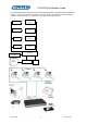
[C] Printer – a 25-pin D-type female connector for connecting the Vi-POSCON printer.
[D] 485 – a 9-pin D-type RS-232/RS485 female connector for future use (to allow the connection of
multiple Vi-POSCON controllers).
[E] 232A and 232B – two 9-pin D-type RS-232 male connectors.
232A is used to output the Synchronizing Clock data to other equipment.
232B is for future use.
The RS-232 output is fixed
at 9600, N, 8, 1.
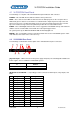
[F] Data1 through Data4 – four 9-pin D-type RS-232/RS-485 male connectors for input from the
Printer Port Interfaces. (The Printer Port Interfaces can output data in either RS-232 or RS-485.)
Wire
Colour
RS-232
Data In
Pin
Wire
Colour
RS-485
Data In
Pin
RED 2 – RXD 4 – RX+
BLACK 5 – GND 5 – GND
9 – RX-
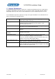
Note: Jumpers on the Vi-POSCON main PCB must be set to allow RS-232 or RS-485 data input. RS-
232 is the default setting for all four interface data input channels. Interface data input channels may
be set in any combination of RS-232 or RS-485 input.
RS-232/RS-485 Interface Data Input
Data
Input
Channel
Jumper RS-232 Data Input RS-485 Data Input
1 P12
2 P11
3 P10
4 P9
For RS-232, set
jumper towards rear
of unit (default).
For RS-485, set jumper
towards front of unit.
[G] AUX – a BNC connector for future use.
[H] Main Mon. – a BNC connector for the main monitor when Vi-POSCON is configured as a
standalone system (more than one camera/register input with output to a single DVR/monitor).
[I] Video Input (1 through 4) – four BNC connectors for camera input.