
User Manual


Videoswitch 9 Pos601a.doc
Vi-POSCON Installation Guide
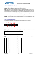
4.1 Vi-POSCON Front Panel
The following is a escription of the Vi-POSCON front panel indicators and connector.
POWER – This red LED, when lit, indicates that the unit is powered on.
DATA – These four tri-colour LEDs are linked to the four data input ports on the rear panel. These
LEDs flash green as data is received at the associated interface input; they turn steady red as and
when an event occurs, reverting to flashing green once the period of time defined for the event has
lapsed. If no data is being received at a particular port then the associated LED is not lit.
EVENT – This red LED lights when the first event is logged into Vi-POSCON memory and remains lit
until the user has reviewed that event and all other subsequent logged events.
On system power-up, the DATA and EVENT LEDs momentarily light red.
MOUSE – This is a mini-DIN socket for connecting a PS/2 mouse to the Vi-POSCON System. A tick-
mark indicates the location of the connector's key.
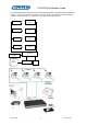
4.2 Vi-POSCON Rear Panel
The following is an illustration and description of the Vi-POSCON rear panel connectors.
[A] Power Input – a DIN connector for the power supply unit (PSU). The following table identifies the
power supplies to be used with the Vi-POSCON Systems.
For Vi-POSCON Systems
in:
Use Power Supply Part
Number:
North America 590001
Europe 590002
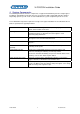
[B] Alarms I/O & VCR/DVR – a 37-pin D-type female connector for alarm inputs, relay outputs, and
DVR.
Pin Assignment Pin Assignment
1 Relay 1 NO* 20 Relay 1 COM
2 Relay 1 NC* 21 unassigned
3 Relay 2 NO 22 Relay 2 COM
4 Relay 2 NC 23 unassigned
5 Relay 3 NO 24 Relay 3 COM
6 Relay 3 NC 25 unassigned
7 Relay 4 NO 26 Relay 4 COM
8 Relay 4 NC 27 unassigned
9 Relay 5 NO 28 Relay 5 COM
10 Relay 5 NC 29 unassigned
11 unassigned 30 unassigned
12 unassigned 31 unassigned
13 unassigned 32 unassigned
14 unassigned 33 unassigned
[A] [B] [E] [F] [G] [I]
[C] [D] [H] [J]