HGV Extra-large sized housing EN English - Instructions manual IT Italiano - Manuale di istruzioni FR Francais - Manuel d'instructions DE Deutsch - Bedienungslanleitung
HGV Extra-large sized housing EN English - Instructions manual
Contents ENGLISH 1 About this manual......................................................................................................... 3 1.1 Typographical conventions................................................................................................................................. 3 2 Notes on copyright and information on trademarks................................................. 3 3 Safety rules.........................................................................................
1 About this manual 1.1 Typographical conventions DANGER! High level hazard. Risk of electric shock; disconnect the power supply before proceeding with any operation, unless indicated otherwise. gg WARNING! Medium level hazard. This operation is very important for the system to function properly. Please read the procedure described very carefully and carry it out as instructed. hh INFO Description of system specifications.
EN - English - Instructions manual 4 Identification 4.1 Product description and type designation Large-size housing, designed to allow mounting of the largest "zoom cctv lenses" on the market; for example PENTAX 55x, FUJINON 60x, PENTAX 18x, COMPUTAR 30x, COMPUTAR 50x … and many others. Its water-tightness is assured by the neoprene rubber gaskets, by 4 M16 cable glands equipped with relative gaskets and by the stainless steel screws that guarantee its permanent closure.
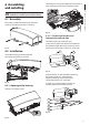
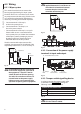
6 Assembling and installing Lift the upper casing with integrated sunshield and leave it hanging to the sturdy anchoring cable. EN - English - Instructions manual Only specialised personnel should be allowed to assemble and install the device. hh 6.1 Assembly Mount the sunshield to the housing with the 4 screws and washers provided as standard. Fig. 04 6.2.1.1 Fastening of the lens and camera to the internal slide Hook the camera (02) to the lens (01). Fig.
EN - English - Instructions manual Fasten the aluminium plate (01) on the slide by means of the 2 M4 screws and relative washers (02). 01 02 01 03 02 Fig. 07 Fig. 10 Then fasten the two small plates with the M4 screw (01). Now proceed with the operations shown in Fig. 07, page 6 and Fig. 08, page 6. 6.2.2 Positioning of the inner slide Shift the inner slide with lens and camera already fastened into the wanted position and secure it by means of the four washers and screws provided. 01 Fig. 08 6.
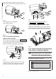
Replace the standard plate by undoing the 4 fastening screws. Position the blade in the stop position. EN - English - Instructions manual Fig. 16 The correct adjustment must allow the return of the blade to the stop position going to the end stop on the casing’s plate. hh Fig. 13 Position the EPDM gaskets between the new plate and the housing before fastening it to the housing itself. Fasten the whole assembly by means of the washer and nut. Fig. 17 6.2.
6.3 Wiring In the 230Vac model, a strap must be applied between the 3 conductors to avoid the risk of accidental contacts between the phase wire and the accessible conductive part. gg EN - English - Instructions manual 6.3.1 Wiper system This section describes how to connect the housings equipped with glass wiper system For these versions it is not necessary to mount any component inside the casing since the units are supplied complete with all the elements necessary, according to the model requested.
7.2 Cleaning 7.1 Maintaining 7.2.1 Window and plastic cover cleaning (PC) 7.1.1 Replacing of the glass in case of damage Loosen the 5 nuts. Surface dirt should be rinsed away with water and then the window cleaned with a neutral soap diluted with water, or specific products for spectacle lens cleaning. These should be applied with a soft cloth. Avoid ethyl alcohol, solvents, hydrogenated hydrocarbide, strong acid and alkali. Such products may irreparably damage the surface.
9.3 Electrical Camera power supply -- IN 100-240Vac - OUT 12Vdc, 50/60 Hz, 1A Integrated wiper -- IN 230Vac, consumption 7W max 9.4 Environment -- IN 24Vac, consumption 7W max Indoor / Outdoor Heater Ton 15°C+/-3°C (59°F +/-5°F) Toff 22°C+/-3°C (71°F +/-5°F) Operating temperature with heater: -20°C / +50°C (-4°F / +122°F) -- IN 115/230Vac, fan assisted triple heater, consumption 150W 9.
HGV Custodia stagna extra large IT Italiano - Manuale di istruzioni
Sommario ITALIANO 1 Informazioni sul presente manuale............................................................................. 3 1.1 Convenzioni tipografiche..................................................................................................................................... 3 2 Note sul copyright e informazioni sui marchi commerciali....................................... 3 3 Norme di sicurezza.............................................................................................
1 Informazioni sul presente manuale 1.1 Convenzioni tipografiche PERICOLO! Pericolosità elevata. Rischio di scosse elettriche. Togliere l'alimentazione prima di procedere con le operazioni, salvo diversa indicazione. gg ATTENZIONE! Pericolosità media. L'operazione è molto importante per il corretto funzionamento del sistema. Si prega di leggere attentamente la procedura indicata e di eseguirla secondo le modalità previste. hh INFO Descrizione delle caratteristiche del sistema.
4 Identificazione IT - Italiano - Manuale di istruzioni 4.1 Descrizione e designazione del prodotto Custodia di grandi dimensioni, progettata per permette l’inserimento tra i più grandi "zoom cctv lensens" in commercio; ad esempio PENTAX 55x, FUJINON 60x, PENTAX 18x, COMPUTAR 30x, COMPUTAR 50x … e molti altri.
6 Assemblaggio e installazione Sollevare il corpo superiore con tettuccio integrato e lasciarlo appeso al robusto cavo di ancoraggio. L'assemblaggio e l'installazione vanno eseguiti solo da personale specializzato. hh IT - Italiano - Manuale di istruzioni 6.1 Assemblaggio Fissare il tettuccio alla custodia tramite le 4 viti e le 4 rondelle fornite in dotazione. Fig. 04 6.2.1.1 Fissaggio dell’ottica e telecamera alla slitta interna Agganciare la telecamera (02) all’ottica (01). Fig.
01 02 01 03 02 Fig. 07 Fig. 10 Fissare poi le due piastrine con la vite M4 (01). Procedere quindi con le operazioni come in Fig. 07, pagina 6 e Fig. 08, pagina 6. 6.2.2 Posizionamento della slitta interna 01 Far scorrere la slitta interna con ottica e telecamera già fissate nella posizione desiderata e fissarla tramite le 4 rondelle e viti in dotazione Fig. 08 6.2.1.2 Posizionamento del distanziale H20 nella slitta interna Effettuare le stesse operazioni indicate in Fig. 05, pagina 5.
Sostituire la piastra standard svitando le 4 viti di fissaggio Mettere la spazzola nella posizione di riposo. IT - Italiano - Manuale di istruzioni Fig. 16 La regolazione corretta deve permettere alla spazzola di ritornare nella posizione di riposo andando in battuta sulla piastra del corpo. hh Fig. 13 Posizionare la guarnizione in EPDM tra la nuova piastra e la custodia prima di fissarla alla custodia Fissare il tutto tramite rondella e dado. Fig. 17 Fig. 14 6.2.
6.3 Cablaggi Nella versione alimentata a 230Vac occorre applicare una fascetta tra i 3 conduttori per evitare il rischio di contatti accidentali tra filo di fase e parte conduttrice accessibile. gg 6.3.1 Sistema tergicristallo IT - Italiano - Manuale di istruzioni Questa sezione descrive come collegare le custodie munite di sistema tergicristallo.
7 Manutenzione e pulizia 7.2 Pulizia 7.1 Manutenzione 7.2.1 Pulizia del vetro e delle parti in plastica (PC) Allentare i 5 dadi. Si consigliano saponi neutri diluiti con acqua o prodotti specifici per la pulizia delle lenti degli occhiali con l’utilizzo di un panno morbido. IT - Italiano - Manuale di istruzioni 7.1.1 Sostituzione del vetro in caso di rottura Sono da evitare alcool etilico, solventi, idrocarburi idrogenati, acidi forti e alcali.
9.3 Elettrico Alimentatore per telecamera -- IN 100-240Vac - OUT 12Vdc, 50/60 Hz, 1A Tergicristallo integrato -- IN 230Vac, consumo 7W max 9.4 Ambiente -- IN 24Vac, consumo 7W max Interno / Esterno Riscaldamento Ton 15°C+/-3°C Toff 22°C+/-3°C Temperatura d’esercizio con riscaldamento: -20°C / +50°C -- IN 115/230Vac, triplo riscaldamento assistito da ventole, consumo 150W 9.
HGV Le caisson le plus grand de la gamme FR Français - Manuel d'instructions
Sommaire FRANÇAIS 1 À propos de ce mode d’emploi..................................................................................... 3 1.1 Conventions typographiques............................................................................................................................. 3 2 Notes sur le copyright et informations sur les marques de commerce..................... 3 3 Normes de securité........................................................................................................
1 À propos de ce mode d’emploi Avant d’installer et d’utiliser cet appareil, veuillez lire attentivement ce mode d’emploi. Conservez-le à portée de main pour pouvoir vous y reporter en cas de besoin. DANGER! Risque élevé. Risque de choc électrique. Sauf indication contraire, sectionner l’alimentation avant de procéder à toute opération. gg ATTENTION! Risque moyen.
4 Identification FR - Francais - Manuel d'instructions 4.1 Description et désignation du produit Caisson grandes dimensions projeté pour être intégré aux plus grands zoom cctv lensens disponibles dans le commerce, comme par exemple PENTAX 55x, FUJINON 60x, PENTAX 18x, COMPUTAR 30x, COMPUTAR 50x, etc., ainsi qu’à de nombreux autres modèles. Son étanchéité est assurée par les garnitures en caoutchouc néoprène, par 4 pressecâbles M16 avec garnitures et par des vis en acier inox assurant une fermeture fiable.
6 Assemblage et installation Soulever la structure supérieure avec toit pare-soleilt intégré et la pendre au robuste câble d’ancrage. L’assemblage et l’installation doivent exclusivement être effectués par un personnel spécialisé. hh FR - Francais - Manuel d'instructions 6.1 Assemblage Fixer le toit pare-soleil au caisson au moyen des 4 vis et des 4 rondelles fournies. Fig. 04 6.2.1.1 Fixation de l’optique et de la caméra à la glissière interne Fixer la caméra (02) à l’optique (01).
Fixer la plaque en aluminium (01) sur la glissière au moyen des 2 vis M4 et de leurs rondelles (02). 01 02 03 02 Fig. 07 Fig. 10 Fixer ensuite les deux platines avec la vis M4 (01). Proceder avec les operations comme dans Fig. 07, page 6 et Fig. 08, page 6. 6.2.2 Positionnement de la glissière interne 01 Faire glisser la glissière interne avec l’optique et la caméra déjà fixées en position et la fixer avec les quatre rondelles et les vis fournies. Fig. 08 6.2.1.
Remplacer la plaque standard en desserrant les 4 vis de fixation. Placer le balai en position de repos. FR - Francais - Manuel d'instructions Fig. 16 Un réglage correct doit permettre au balai de revenir en position de repos en entrant en contact avec la plaque de la structure. hh Fig. 13 Positionner la garniture en EPDM entre la nouvelle plaque et le caisson avant de la fixer au caisson. Fixer l’ensemble avec rondelle et écrou. Fig. 17 6.2.5 Fixation de la platine avec buse Fig.
6.3 Câblages Dans la version alimentée à 230Vac, prévoir un collier entre les 3 conducteurs pour éviter tout contact accidentel entre le fil de phase et la partie conductrice et accessible. gg 6.3.1 Système d’essuie-glace FR - Francais - Manuel d'instructions Cette partie décrit le mode de connexion des caissons équipés de système essuie-glace.
7 Entretien et nettoyage 7.2 Nettoyage 7.1 Entretien 7.2.1 Entretiens de la vitre et des parties en plastique (PC) 7.1.1 Remplacement du verre en cas de rupture Desserrer les 5 écrous Nous conseillons l’emploi, avec un chiffon souple, de savons neutres dilués avec de l’eau ou bien de produits spécifiques pour le nettoyage des vitres de lunettes. 8 Élimination des déchets Ce symbole et le système de recyclage ne sont appliqués que dans les pays UE et non dans les autres pays du monde. nn Fig.
9.3 Électrique Alimentation pour camèra -- IN 100-240Vac - OUT 12Vdc, 50/60 Hz, 1A Essuie-glace intégré -- IN 230Vac, consommation 7W max 9.4 Environnement -- IN 24Vac, consommation 7W max Intérieur / Extérieur Chauffage Ton 15°C+/-3°C Toff 22°C+/-3°C Température d’exercice avec chauffage: -20°C / + 50°C -- IN 115/230Vac, triple chauffage avec ventilateur, consommation 150W 9.
HGV Das grösste Gehäuse des Lieferprogramms DE Deutsch - Bedienungslanleitung
Inhaltsverzeichnis DEUTSCH 1 Allgemeines................................................................................................................... 3 1.1 Schreibweisen.......................................................................................................................................................... 3 2 Anmerkungen zum Copyright und Informationen zu den Handelsmarken............. 3 3 Sichereitsnormen..............................................................................
1 Allgemeines Lesen Sie bitte vor dem Installieren und dem Verwenden dieses Gerätes die Bedienungsanleitung sorgfältig durch. Bewahren Sie sie zum späteren Nachschlagen auf. 1.1 Schreibweisen gg ACHTUNG! Mittlere Gefährdung. Der genannte Vorgang hat große Bedeutung für den einwandfreien Betrieb des Systems: es wird gebeten, sich die Verfahrensweise anzulesen und zu befolgen. hh ANMERKUNG Beschreibung der Systemmerkmale.
4 Identifizierung DE - Deutsch - Bedienungslanleitung 4.1 Beschreibung und Bezeichnung des Produktes 5 Vorbereitung des Produktes auf den Gebrauch Überdimensioniertes Gehäuse für die Aufnahme der größten im Handel erhältlichen "Zoom cctv lenses"; etwa PENTAX 55x, FUJINON 60x, PENTAX 18x, COMPUTAR 30x, COMPUTAR 50x … und viele andere. hh Dichtungen aus Neoprengummi, 4 Kabelhalter M16 samt Dichtungen und Schrauben aus rostfreiem Stahl schließen das Gehäuse hermetisch ab. 5.
6 Zusammenbau Und Installation Den oberen Korpus mit der integrierten Haube anheben und an das robuste Verankerungskabel hängen. Zusammenbau und Installation sind Fachleuten vorbehalten. hh 6.1 Zusammenbau Das Sonnenschutzdach mit den 4 Schrauben und 4 Unterlegscheiben am Gehäuse befestigen. 6.2.1.1 Befestigung der Optik und der Kamera am Innenschlitten Die Kamera (02) mit der Optik (01) zusammenstecken. Fig. 01 6.
Die Aluminiumplatte (01) mit den 2 Schrauben M4 und den zugehörigen Unterlegscheiben (02) auf dem Schlitten befestigen. 01 02 03 02 Fig. 07 Anschließend die beiden Plättchen mit der Schraube M4 fixieren, wie in der Abbildung gezeigt (01). 01 Fig. 10 Führen Sie die Bedingungen wie in Fig. 07, Seite 6 und Fig. 08, Seite 6 weiter aus. 6.2.
Die Standardplatte ersetzen, indem man die 4 Befestigungsschrauben ausdreht. Das Wischerblatt in Ruhestellung bringen. DE - Deutsch - Bedienungslanleitung Fig. 16 Das Wischerblatt ist dann richtig eingestellt, wenn das Blatt in die Ruhestellung zurückkehren kann und dabei an der Korpusplatte anschlägt. hh Fig. 13 Die Dichtung aus EPDM zwischen der neuen Platte und dem Gehäuse positionieren, bevor Erstere endgültig am Gehäuse fixiert wird.
6.3 Verkabelungen In der Ausführung mit 230Vac Versorgungsspannung muss zwischen den 3 Leitern eine Schelle angebracht werden. So wird das Risiko versehentlichen Kontaktes zwischen dem Phasendraht und dem zugänglichen Teil des Leiters ausgeschaltet. gg 6.3.1 Scheibenwischanlage Dieser Abschnitt beschreibt, wie Gehäuse mit Scheibenwischer angeschlossen werden.
7 Wartung und Reinigung 7.2 Reinigung 7.1 Wartung 7.2.1 Reinigung des Glases und der Kunststoffteile (PC) 7.1.1 Ersetzung der Scheibe bei Glasbruch Die 5 Muttern lockern. Es werden empfohlen verwässerte neutrale Seifen oder spezifische Produkte zur Reinigung der Brillenlinsen zusammen mit einem weichen Tuch. Zu vermeiden sind Äthylalkohol, Lösungsmittel, hydrierte Kohlenwasserstoffe, starke Säuren und Alkali. Diese Produkte können die behandelte Oberfläche beschädigen.
9.3 Elektrik Kameranetzteil -- IN 100-240Vac - OUT 12Vdc, 50/60 Hz, 1A Vorinstallierter Wischer -- IN 230Vac, Verbrauch 7W max 9.4 Umgebung -- IN 24Vac, Verbrauch 7W max Für innere / äußere Installationen Heizung Ton 15°C+/-3°C Toff 22°C+/-3°C Betriebstemperatur mit Heizung: -20°C / +50°C -- IN 115/230Vac, dreifache lüftergestützte Heizung, Verbrauch 150W 9.
VIDEOTEC S.p.A. www.videotec.com Printed in Italy MNVCHGV_0850 HEADQUARTERS ITALY FRANCE UK / IRELAND U.S.A. / CANADA ASIA PACIFIC VIDEOTEC S.p.A. Tel. +39 0445 697411 Fax +39 0445 697414 info@videotec.com VIDEOTEC FRANCE S.A.R.L. Tel. +33 2 32094900 Fax +33 2 32094901 info@videotec-france.com VIDEOTEC UK SALES Tel. +44 0113 815 0047 Fax +44 0113 815 0047 uksales@videotec.com VIDEOTEC SECURITY, Inc. Tel. +1 973 5950788 Fax +1 425 6484289 usasales@videotec.com VIDEOTEC (HK) Ltd Tel.