HTV Aluminium housing for thermal cameras EN English - Instructions manual IT Italiano - Manuale di istruzioni FR Francais - Manuel d'instructions DE Deutsch - Bedienungslanleitung
HTV Aluminium housing for thermal cameras EN English - Instructions manual
Contents EN - English - Instructions manual ENGLISH 1 About this manual......................................................................................................... 3 1.1 Typographical conventions................................................................................................................................. 3 2 Notes on copyright and information on trademarks................................................. 3 3 Safety rules.....................................................
1 About this manual 1.1 Typographical conventions DANGER! High level hazard. Risk of electric shock; disconnect the power supply before proceeding with any operation, unless indicated otherwise. gg WARNING! Medium level hazard. This operation is very important for the system to function properly. Please read the procedure described very carefully and carry it out as instructed. hh INFO Description of system specifications.
EN - English - Instructions manual 5 Preparing the product for use Any change that is not expressly approved by the manufacturer will invalidate the guarantee. hh 5.1 Contents and unpacking When the product is delivered, make sure that the package is intact and that there are no signs that it has been dropped or scratched. 6 Installing and assembling Only specialised personnel should be allowed to install and assemble the device. hh 6.1 Installation 6.1.
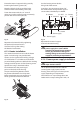
Pass the heating wire under the fixing slide of the camera. Move the slide, by sliding it until the holes coincide with the slide locking screws (02). Insert the 2-pin connector at the end of the cable into the correspondent support circuit socket, identified by J3 HEATER. Fasten the camera with the 1/4" screw. If necessary, use the supplied spacers to correctly position the camera and optics (03).
When the circuit is powered by an external source care must be taken to the type of voltage used and, depending on requirements, to the correct power supply kit. When installing the optional camera power supply it is not necessary to remove any previously installed component. Fig. 05 IN 100-240Vac - OUT 12Vdc. 6.1.5 Changing the germanium glass Fig. 06 IN 230Vac - OUT 24Vac. The other has an input voltage of 230Vac and an output voltage of 24Vac, 400mA. Germanium glass has two colours.
Technical specifications 7.1 Cleaning IR glass and plastic parts 9.1 General Surface dirt should be rinsed away with water and then the window cleaned with a neutral soap diluted with water, or specific products for spectacle lens cleaning. These should be applied with a soft cloth. Sunshield in ABS When cleaning the window with the IR filter, take extra care not to scratch or damage the outer surface treated with carbon coating.
Technical drawings The values are in millimeters. jj 514 27 98 131 160 176 70 76 115 145 USABLE AREA 13 14 70 A 88 163 140 100 412 A 260 76 117.5 400 22.5 212.5 70 40 187.5 112.5 60 87.5 Fig. 11 62 39 = 13 225 400 87.5 HTV VIDEOTEC S.p.A. www.videotec.com Printed in Italy MNVCHTV32_0919_EN 140 = 39 52.
HTV Custodia in alluminio per telecamere termiche IT Italiano - Manuale di istruzioni
Sommario ITALIANO 1 Informazioni sul presente manuale............................................................................. 3 IT - Italiano - Manuale di istruzioni 1.1 Convenzioni tipografiche..................................................................................................................................... 3 2 Note sul copyright e informazioni sui marchi commerciali....................................... 3 3 Norme di sicurezza......................................................
1 Informazioni sul presente manuale 1.1 Convenzioni tipografiche PERICOLO! Pericolosità elevata. Rischio di scosse elettriche. Togliere l'alimentazione prima di procedere con le operazioni, salvo diversa indicazione. gg ATTENZIONE! Pericolosità media. L'operazione è molto importante per il corretto funzionamento del sistema. Si prega di leggere attentamente la procedura indicata e di eseguirla secondo le modalità previste. hh INFO Descrizione delle caratteristiche del sistema.
5 Preparazione del prodotto per l'utilizzo Qualsiasi cambiamento non espressamente approvato dal costruttore fa decadere la garanzia. IT - Italiano - Manuale di istruzioni hh 5.1 Contenuto e disimballaggio Alla consegna del prodotto verificare che l'imballo sia integro e non abbia segni evidenti di cadute o abrasioni. In caso di evidenti segni di danno all'imballo contattare immediatamente il fornitore.
01 03 Passare il filo del riscaldamento sotto la slitta per il fissaggio della telecamera. Inserire il connettore a 2 poli posto all’estremità del cavo nel suo corrispondente sul circuito di appoggio, indicato con la scritta J3 HEATER. J2 - OUT J5 - Camera J8 - Ventilatore OUT J2 - Morsetto J1 - IN IT - Italiano - Manuale di istruzioni Estrarre la slitta interna di appoggio svitando parzialmente le viti di fissaggio (01).
Fig. 05 IN 100-240Vac - OUT 12Vdc. Alimentando il circuito da una sorgente esterna è necessario prestare attenzione al tipo di tensione utilizzata e a seconda delle esigenze, il kit di alimentazione corretto. Per montare l’opzione alimentatore non è necessario rimuovere alcun componente preinstallato. hh 6.1.5 Installazione ricambio vetro al germanio Il vetro al germanio presenta due colorazioni.
7 Manutenzione e pulizia 9 Dati tecnici 7.1 Pulizia del vetro IR e delle parti in plastica 9.1 Generale Si consigliano saponi neutri diluiti con acqua o prodotti specifici per la pulizia delle lenti degli occhiali con l’utilizzo di un panno morbido. Tettuccio in ABS hh 8 Smaltimento dei rifiuti Questo simbolo e il sistema di riciclaggio sono validi solo nei paesi dell'EU e non trovano applicazione in altri paesi del mondo.
10 Disegni tecnici I valori espressi sono in millimetri. jj 514 27 98 131 160 176 70 76 88 AREA UTILE 13 14 70 A 115 145 163 140 100 412 A 260 76 117.5 400 22.5 212.5 70 40 187.5 112.5 60 87.5 Fig. 11 62 39 = 13 225 400 87.5 HTV VIDEOTEC S.p.A. www.videotec.com Printed in Italy MNVCHTV32_0919_IT 140 = 39 52.
HTV Caisson en aluminium pour cameras thermiques FR Français - Manuel d'instructions
Sommaire FRANÇAIS 1 À propos de ce mode d’emploi..................................................................................... 3 FR - Francais - Manuel d'instructions 1.1 Conventions typographiques............................................................................................................................. 3 2 Notes sur le copyright et informations sur les marques de commerce..................... 3 3 Normes de securité................................................................
1 À propos de ce mode d’emploi • L’installation et l’entretien du dispositif doivent être exclusivement être effectués par un personnel technique qualifié. Avant d’installer et d’utiliser cet appareil, veuillez lire attentivement ce mode d’emploi. Conservez-le à portée de main pour pouvoir vous y reporter en cas de besoin. • Ne pas utiliser de câbles d’alimentation usés ou endommagés. DANGER! Risque élevé. Risque de choc électrique.
5 Préparation du produit en vue de l’utilisation FR - Francais - Manuel d'instructions Toute modification non approuvée expressément par le fabricant entraînera l’annulation de la garantie. 6 Installation et assemblage L’installation et l’assemblage doivent exclusivement être effectués par un personnel spécialisé. hh hh 5.1 Contenu et déballage 6.1 Installation Lors de la livraison du produit, vérifier que l’emballage est en bon état et l’absence de tout signe évident de chute ou d’abrasion. 6.1.
Extraire la glissière interne d’appui en dévissant partiellement les vis de fixation (01). Déplacer la glissière en la faisant glisser jusqu’à ce que les trous coïncident avec les vis de blocage de celle-ci (02). Fixer la caméra avec la vis de 1/4". Si nécessaire, utiliser les entretoises fournies pour placer de façon correcte la caméra et l’optique (03). 03 Insérer le connecteur à 2 pôles placé en bout de câble dans son emplacement sur le circuit d’appui, indiqué par J3 HEATER.
En alimentant le circuit à partir d’une source externe, il faut faire attention au type de tension utilisée et, selon les exigences, au bon kit d’alimentation. Pour monter l’option alimentateur, il n’est nécessaire d’enlever aucun composant déjà installé. hh 6.1.5 Installation vitre au germanium de remplacement Fig. 05 IN 100-240Vac - OUT 12Vdc. Fig. 06 IN 230Vac - OUT 24Vac. La vitre au germanium présente deux colorations.
7 Entretien et nettoyage 9 Données techniques 7.1 Nettoyage de la vitre IR et des parties en plastique 9.1 Généralités Nous conseillons l’emploi, avec un chiffon souple, de savons neutres dilués avec de l’eau ou bien de produits spécifiques pour le nettoyage des verres de lunettes. Toit pare-soleil en ABS hh 8 Élimination des déchets Ce symbole et le système de recyclage ne sont appliqués que dans les pays UE et non dans les autres pays du monde.
10 Dessins techniques Les valeurs sont entendues en millimètres. jj 514 27 98 131 160 176 70 76 115 145 SURFACE UTILE 13 14 70 A 88 163 140 100 412 A 260 76 117.5 400 22.5 212.5 70 40 187.5 112.5 60 87.5 Fig. 11 62 39 = 13 225 400 87.5 HTV VIDEOTEC S.p.A. www.videotec.com Printed in Italy MNVCHTV32_0919_FR 140 = 39 52.
HTV Aluminiumgehäuse für Wärmebildkameras DE Deutsch - Bedienungslanleitung
Inhaltsverzeichnis DEUTSCH 1 Allgemeines................................................................................................................... 3 1.1 Schreibweisen.......................................................................................................................................................... 3 DE - Deutsch - Bedienungslanleitung 2 Anmerkungen zum Copyright und Informationen zu den Handelsmarken............. 3 3 Sichereitsnormen.........................................
1 Allgemeines • Die Installation und Wartung der Vorrichtung ist technischen Fachleuten vorbehalten. Lesen Sie bitte vor dem Installieren und dem Verwenden dieses Gerätes die Bedienungsanleitung sorgfältig durch. Bewahren Sie sie zum späteren Nachschlagen auf. • Vor technischen Eingriffen am Gerät muss die Stromversorgung unterbrochen werden. 1.1 Schreibweisen ACHTUNG! Mittlere Gefährdung.
5 Vorbereitung des Produktes auf den Gebrauch Jede vom Hersteller nicht ausdrücklich genehmigte Veränderung führt zum Verfall der Gewährleistungsrechte. DE - Deutsch - Bedienungslanleitung hh 5.1 Inhalt und Entfernen der Verpackung Bei der Lieferung des Produktes ist zu prüfen, ob die Verpackung intakt ist oder offensichtliche Anzeichen von Stürzen oder Abrieb aufweist. 6 Installation und Zusammenbau Installation und Zusammenbau sind Fachleuten vorbehalten. hh 6.1 Installation 6.1.
Den internen Auflageschlitten herausziehen, indem man die Befestigungsschrauben teilweise löst (01). Reichen Sie den Heizungsdraht unter dem Kamerabefestigungsschlitten. Nun den Schlitten soweit gleiten lassen, bis seine Bohrungen mit den Befestigungsschrauben übereinstimmen (02). Befestigen Sie die Kamera mit der 1/4"-Schraube. Falls erforderlich, kann die Kamera samt Optik mit Hilfe der bei liegenden Paßstücke ausgerichtet werden (03).
Die Alternative ist ein anderer Typ des Netzteils mit einer Eingangsspannung von 230Vac bei einer Ausgangsspannung von 24Vac, 400mA. IN 100-240Vac - OUT 12Vdc. 6.1.5 Einbau des GermaniumAustauschglases Das Germaniumglas weist zwei Farbtöne auf. Innerhalb des Gehäuses verändert sich wegen einer reflexmindernden Schicht die Farbe mit der Ausrichtung. Auf der Außenseite ist es wegen der kratzfesten Schicht hingegen dunkelgrau. Für den Einbau des Austauschglases siehe Fig. 9. Fig. 06 IN 230Vac - OUT 24Vac.
7 Wartung und Reinigung 9 Technische Daten 7.1 Reinigung der IR-Scheibe und der Kunststoffteile 9.1 Allgemeines Es werden empfohlen verwässerte neutrale Seifen oder spezifische Produkte zur Reinigung der Brillenlinsen zusammen mit einem weichen Tuch. Sonnenschutzdach aus ABS hh 8 Müllentsorgungsstellen Dieses Symbol und das entsprechende Recycling-System gelten nur für EULänder und finden in den anderen Ländern der Welt keine Anwendung.
10 Technische Zeichnungen Maßangabe in Millimeter. jj 514 27 98 131 160 176 70 76 115 145 NUTZFLÄCHE 13 14 70 A 88 163 140 100 412 A 260 76 117.5 400 22.5 212.5 70 40 187.5 112.5 60 87.5 Fig. 11 62 39 = 13 225 400 87.5 HTV VIDEOTEC S.p.A. www.videotec.com Printed in Italy MNVCHTV32_0919_DE 140 = 39 52.
VIDEOTEC S.p.A. www.videotec.