
Manual


Instructions manual - English - EN
3
6 Assembling and installing
Only specialised personnel should be
allowed to assemble and install the device.
Before starting any operation, make sure
the power supply is disconnected.
6.1 Installation
6.1.1 Open the box
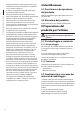
Once the box is open, identify the power input
terminal J1, the output terminals J2 and J3 and the
position of the fuse FUS1.
J2J3
Fig. 1
6.1.2 Connection of the rst illuminator
Connect the power cables of the rst illuminator to
J3, output OUT 1 (the white and black cables in the
illuminator power cable).
The installation is facilitated by removing
the terminal, making the connection and
inserting the terminal once the wiring is
complete.
Install the power supply as near as possible
to the illuminator in order to have short low
voltage cables (shorter than 20m/ 65.6ft).
The remaining 2 wires (red and green) are used for
the remote activation of the illuminator.
3 congurations are possibles:
• Isolate the 2 red and green cables separately if
automatic switch-on is used via the photocell on
the illuminator.
• If you wish to force the illuminator on, short circuit
the 2 cables and isolate them with a terminal.
• Connect the 2 cables to an external clean contact if
you wish to turn the illuminator on remotely with a
clean contact.
Refer to the relative manual for installation and
control of the illuminator.
6.1.3 Connection of the second
illuminator
If present, connect the second illuminator in the
same way as the rst, using terminal J2.
Never connect the remote illuminator
activation cables (red and green wires) to
those of the rst illuminator. If there are 2
illuminators and you wish to check them
with a clean contact, each one must have its
own clean activation contact. Alternatively,
it is recommended to short circuit the red
and green cables separately (illuminator
1 and illuminator 2) and act on the main
power supply (J1) to turn the 2 illuminators
on or o simultaneously via the remote
switch.
6.1.4 Connection of the power supply
line
When commencing installation make sure
that the specications for the power supply
for the installation correspond with those
required by the device.
Make sure the supply voltage is compliant
with the power supply specications (230
Vac or 120 Vac 50/60Hz, depending on the
model purchased).
Use a cable with an adequate cross-section,
depending on the type of system, which
must in any case be between the following
values: 0.5mm²-1.5mm² (0.000775in²-
0.002325in²) (AWG 20-16).